AppIying a voltage to the electromagnet arrows the devices wired to the switch to be controlled. Relays are important as they can be used to control high power Ioads from weak signals or currents.
Another advantage in the use of relays is that the contacts are isolated from the control circuit, meaning a relay can be used to control a high-voltage circuit from a Iow-voltage circuit. The disadvantage is that the coupling between the coil and the contacts is mechanical, Iimiting the speed of response.
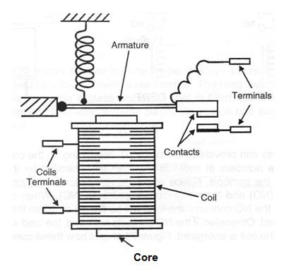
Figure 1 shows the basic construction of a relay as found in many electronic applications.

The coiI is formed by hundreds or thousands of turns of thin, enameled wire. The contacts are designed to control high currents based on the finaI use of the device.
Symbols and Víews
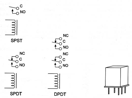
Figure 2 shows the symbols and views of the relays used in common electronic applications.

A relay can provide SPDT or DPDT depending on the contact placement. The numbers of contacts that can be controlled by the relay are shown in the symbols.
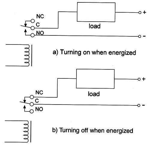
Notice when the relay can have “normaIIy open” contacts (NO) and “normally closed” contacts (NC). When controlling a Ioad from the NO contacts, the Ioad wiII be turned on when the relay's coiI is energized. Otherwise, if the NC contacts are used, the Ioad will be turned off when the coiI is energized. Figure 3 shows how these contacts should be used.

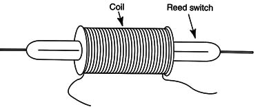
Figure 4 shows another important type of relay- the reed-relay. This relay is formed by a coil involving a reed switch. The reed switch is formed by metal plates inside a glass enclosure that is fílled with an inert gas.
When a magnetic field acts on these plates, they touch one another, closing the circuit.

Specifications
When replacing a relay, the electrician must take care to observe these specifications:
A. Coil specifications
The current that turns a relay on is given by the coil specifications. The relay can be specified by the voltage to be applied to the coil in volts and the current, or by its ohmic resistance. For example a 12 V x 50 mA relay can also be indicated as a 240-ohm relay for 12 V.
B. Contact specification
This is the amount of current (and the voltage of the external circuit) that can be controlled by the relay.
C. Contact configuration
This is given by the number of contacts and their type-SPST or DPDT.
Where they are found
In electric circuits, the reader usually finds relays controlling high electric currents such as in motors, Iamps, etc. In electronic circuits it is most common to fínd smaII relays controlling small currents.
Small relays can be found in alarms controlling the siren, Iamps, or other Ioads. In automatic doors, remote controls, and other applications, relays interface the control circuit with the controlled Ioad.
Testing
Two kinds of tests can be done in a relay:
A. Coil: The state of the coil can be verified by a multimeter. A good coil presents resistances between some ohms and 10,000 Ω. This probe doesn't indicate a shoned coiI.
B. Contacts: The contacts are tested by applying a voltage to the coiI and measuring the resistance when they close. This resistance must be almost zero when tested with a common multimeter.


