The difference between the switches used in common electric installations and cars is not important. In electronic equipment the switches, in many cases, are used to control many currents at the same time. The design also depends the applications.
Symbols and Types
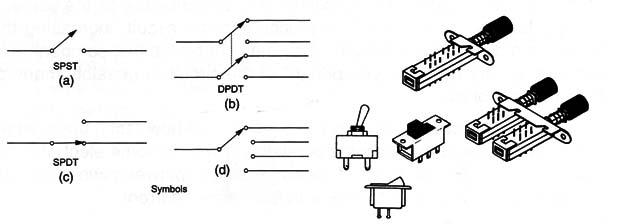
Figure 1 shows the symbols and types of the main types of switches found in electronic circuits. The symbol indicates what the switch makes.

For instance, (a) shows an SPST (Single-Pole Single-Throw), which is a switch that controls the current flow in only one circuit (single-pole). As the name suggests, this switch controls one circuit turning the current on and off.
A DPDT (Double-Pole Double-Throw) is shown in (b). This switch can control the current in two independent circuits (double-pole) transferring it to one or another circuit (double throw). The switches also are different in the way they are operated. A circuit can have slide switches (b), toggle switches (c), and rotary switches (d).
Some special switches are also shown in Figure 1, such as thumbwheel types, pushbuttons, and subminiatures that are suitable for installation in PCBs (Printed Circuit Boards), etc.
Where they are found
Switches are found in any application where current must be controlled. Every piece of electronic equipment needs at least one switch for its operation-the on/off switch.
Specifications
The switches are identified by the number of poles, the number of positions, the maximum operating voltage, and current.
The poles and positions are indicated by symbols or letters. These are the main types:
SPST-Single-Pole Single-Throw
SPDT-Single-Pole Double-Throw
DPDT-DoubIe-Pole Double-Throw
Maxim um Operating Current and Voltage
The maximum operating current is indicated in amperes (A). Never use a switch in a circuit with a current larger than the maximum recommended. The contacts can heat causing problems. The maximum voltage is indicated in volts (V).
How to Test
An open switch must present a very high resistance (near infinite) and when closed a very low resistance (near zero). To test a switch, take a simple continuity measurement using a multimeter in the lowest resistance scale. It is important, in some cases, to make a visual inspection: a switch with contact problems due to excess current can present some visible signs such as deformations or dark areas in the contact.


