Originally this article was written in Portuguese and published in a Brazilian Magazine. After, it was translated into English and then included in my book Mechatronics for the Evil Genius – TAB – 2006. You can buy this book by Amazon and find many other interesting projects.
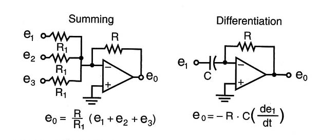
Operational amplifiers were so efficient at performing tasks such as addition, subtraction, multiplication, division, integration, and differentiation that they are still used today in many applications that use analog signals. Although the operational amplifiers were created to be used for computing, upgraded forms have been created to perform many other applications. Figure 1 shows the diagram adopted to represent an operational amplifier (OA) and some of its configurations.
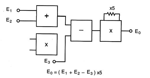
Converting numbers and sending them as voltages across the circuits, the computer performed mathematical operations and then sent the results to some kind of receiver, as shown in Figure 2.
Analog computers have many deficiencies that digital computers don’t present. At each operation the possibility of errors is introduced, which of course would affect the final results. The more operations completed, the greater the chances of having an error affect the results, and therefore the greater the number of errors.
Another problem is speed. Analog computers can’t perform a large number of operations simultaneously, making them slow and impossible to use in complex calculations.
Analog computers can be compared to slide rules in their operating principle, as they were soon replaced by modern electronic calculators, which had much greater precision and speed. Figure 3 shows a slide rule used by engineers in the mid-1900s, before scientific calculators and computers were invented.

Although analog computers are not widely used today, simple versions such as the ones proposed in this project can be mounted to show how they operate.
Because they use mechanical and electronic parts, they are considered to be a mechatronic project, while adding a touch of computer science and even mathematics.
What we will describe in this project is how to build a basic small analog computer that, like a mechatronic slide rule, can perform some mathematical operations such as the following:
Addition
Subtraction
Multiplication
Division
Log functions
Square root functions
Powers of 2
Trigonometric functions such as sine, cosine, tangent, and cotangent
Calculations involving PI (?)
Proportional calculus
The circuit is very simple in the basic analog computer but can be upgraded with the use of operational amplifiers and other resources. It can be used for the following objectives:
To show how an analog computer works
To perform simple mathematical calculations
To help students with their homework in mathematics
To understand how an analog conversion is made
To be used in fairs, science shows, and in classes
Our computer
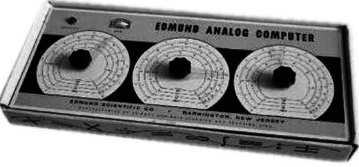
Figure 4 shows the prototype of the analog computer that we will build in the basic version.
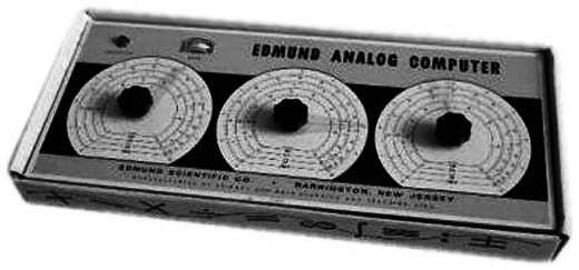
As the reader can see, the basic analog computer has three indicators (attached to the three potentiometers) moving or sliding over a multigraduated scale and an indicator.
Potentiometers 1 and 2 are normally used as data inputs (numbers to be used in a calculation), and potentiometer 3 is adjusted to find the result of the first two potentiometers. When the result of the first two is found, the indicator on the third will show zero.
For instance, if in a multiplication function, you set potentiometer 1 equal to 3 and potentiometer 2 equal to 2, the indicator of potentiometer 3 will show zero (equilibrium) when the potentiometer 3 reaches the position 6 (3 x 2 = 6).
The precision of the results is dependent on many factors:
The precision of the potentiometers and the indicator: Common linear potentiometers are not very accurate devices because they are mechanical. Typically, 5 percent is the normal tolerance rate for these precision components in their scale. If this 5 percent of difference in the results is multiplied by the 3 potentiometers, a great difference in the expected results will occur. Considering the experimental use this difference will not compromise the project. Additionally, the indicator is not necessar- ily precise enough to show exactly when the zero point is reached. This can add another small error to the results.
The precision of scales: The scales are not accurate. Like analog multimeters, the actual size of the pointer indicating the numbers can introduce some degree of error. For example, it might appear as if the pointer is pointing to zero or to one.
The operator: Small differences when positioning the potentiometers to a number can affect the results. This is an error introduced by the operator.
How It Works
The operating principle of the analog computer is based on the potentiometers capability to make analog multiplications. To understand how this works, let’s start from the simple circuit shown in Figure 5.
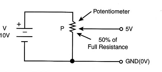
This circuit can convert the mechanical position of the potentiometer’s cursor to an analog voltage. The potentiometer is numbered from 0 to 10, with the center position therefore being 5. If the potentiometer is resting in the center or halfway position (5), this means it represents the halfway point or 50 percent of whatever is registering on the scale. This position equals 50 percent of the battery voltage. If 100 percent of the battery voltage is 10 volts, for instance, the corresponding central position (or halfway point) is 5 volts.
Of course, if we intend to work with larger numbers, we may need to make a mental conversion. For instance, if the number of volts to be converted is 47, we can represent it as 4.7 and convert to 4.7 volts. The decimal point position must of course be considered later when the result is found. Figure 6 shows how to represent other quantities.
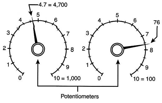
Now let’s go one step ahead, adding another potentiometer to our circuit, as shown in Figure 7.
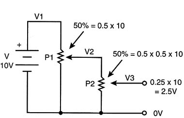
Observing the figure, we can see that the voltage applied to the ends of the second potentiometer is the number selected from the first potentiometer converted to an analog voltage.
So if the second potentiometer is at the central position, or 50 percent of the scale, the voltage in its cursor will be 50 percent of the original 50 percent (0.5 >< 0.5 = 0.25) or 25 percent of the battery voltage. In other words, without the decimal point, the circuit is multiplying 5 x 5 = 25.
This means that if potentiometers 1 and 2 have scales with numbers from 0 to 10, the voltage in the output of the circuit will be the product of the selected number times 10. In other words, a scale registering 0 to 10 volts will represent numbers from 0 to 100.
But how do you read the results? The answer is shown in Figure 8, where a third potentiometer and an indicator are added.
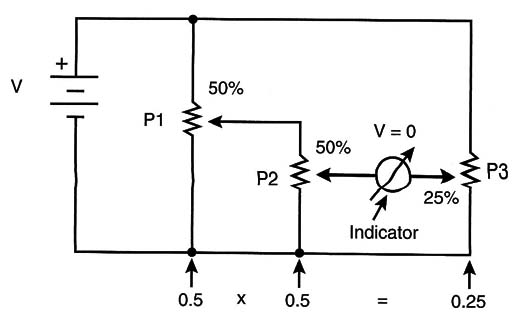
The reader can easily see that if we adjust the third potentiometer (P3) to 0.25 percent on its scale, the voltage in its cursor will be the same as that of the cursor of P2. An indicator placed between those points will indicate zero.
If this potentiometer (P3) is scaled from 0 to 100, the position of its cursor will be the result of the multiplication of the numbers from P1 and P2. This is valid for all numbers, or all points on the scale from P1 and P2, as shown in Figure 9.
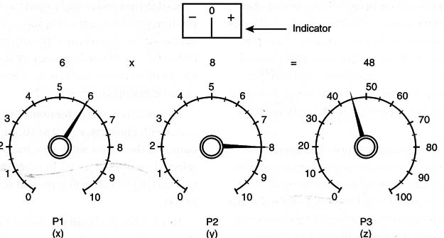
The division of a number can be made with the inverse procedure: The number to be divided is put in P3, the divisor in P2, and the result will appear in P1. When Pl is moved, the circuit detects when the position reaches the result.
The scales, or measurements on the scales, can also be calibrated with other units such as sines, cosines, tangents, and logs. Adjusting P1 to 10 (full scale) and P2 to any angle in the scale of angles, the sine or cosine for this angle can be read in the corresponding scale.
The logarithmic scale is very important because we can use it to make calculations using logs, because an exponentiation is the product of logarithms, and a root is the division of logarithms.
Components Are Critical
An important problem to be considered in this project is that a potentiometer has finite values of resistances. This means that the circuits can be loaded, thereby affecting the final results. Figure 10 shows what happens when one potentiometer reports to another potentiometer that cannot accept the message.
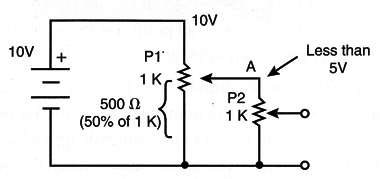
In the figure, a 1,000 ohm potentiometer is coupled to another 1,000 ohm potentiometer. However, if P2 is adjusted to 50 percent of the scale (500 ohm), the voltage in A (in Figure 10) is not 5 volts but less.
What happens is that an equivalent circuit will be formed now by a 500 ohm resistor in series with two other resistors: a 500 ohm resistor formed by the lower half of P1 and 1,000 ohm formed by P2. These two resistors represent a 333 ohm resistor, and the voltage, which we expected to be 5 volts, will be reduced to 3.33 volts, as shown in Figure 11.
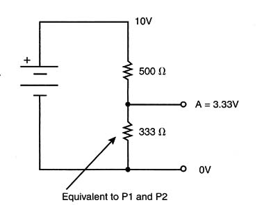
The simplest solution to avoiding this problem is to make P2 as large as possible. If P2 is a 100 k ohm resistor instead of a 1 k ohm, the voltage in P2 will be 4.95 volts, a value almost equal to the expected 5 volts we had hoped for at that point.
Another important point to consider is that the circuit is not dependent on the power supply’s voltage. This is because the voltage is the same in P1, P2, and P3. So any change in one branch of the circuit results in a corresponding similar change in the other branches.
Building the Computer
Figure 12 shows the basic version of the analog computer.
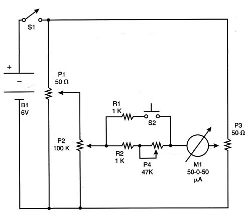
The few components used in the project are placed inside a wooden box, as shown in Figure 13. The author has built a prototype housed in a 40 x 18 x 8 centimeter box.
The power supply is formed by four AA cells. P1 and P3 are wire-wound linear potentiometers. P2 is a common carbon linear potentiometer. The reader must take care with the angle of the cursor. All must be set at 270 degrees to the potentiometers to match the scales suggested in the text.
The indicator is a 50-0-50 µA, with the zero at the center of the scale. This kind of indicator is found in some stereo audio amplifiers to indicate balance.
If the reader can’t find this indicator, he or she can use any 0 to 200 µA common microamperimeter and add a diode bridge so it Will allow currents in both directions. This circuit is shown in Figure 14.
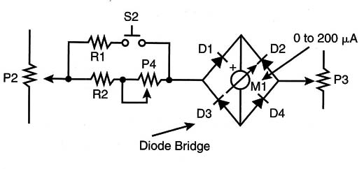
The diodes must be of the germanium type because the silicon type begins to conduct with as little as 0.7 volts. Germanium diodes conduct with 0.2 volts without causing a large sensitivity loss in the indicator.
The ScaIes
The analog computer has the ability to solve problems involving subtraction, addition, multiplication, division, roots, exponentials, logarithmic equations, trigonometric equations, and even combined functions. In the basic version, three dials (X, Y, and Z) are used. Each dial has three scales, or rings of measurement:
- Linear scales a1, a2, and a3 -These are used in operations such as subtraction, addition, multiplication, division, and to extract square roots.
- Logarithmic scales bl, b2, and b3-These are used to make divisions and multiplications by the logarithmic method, to calculate the power of a number, and to find the logarithm of a number.
- Sine and cosine scales c1, c2, and c3-These are used to find the sine and cosine of angles between 0 and 90 degrees.
The scales are made as shown in Figure 15.
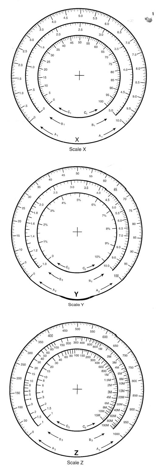
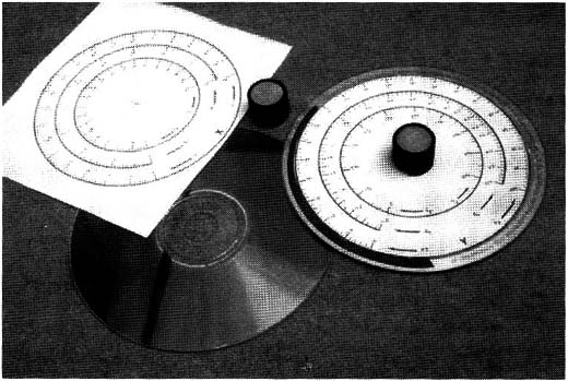
You can save these models and print gluing them to CDs. The CDs are then glued to knobs, such as the ones that fit on potentiometers. The indicators are made from thin wires or even plastic filaments such as the ones found in a synthetic broom. Figure 16 shows how the scales are mounted.
The cell (or battery) holder is placed inside the box, and the on/off switch is placed on the panel. When mounting the potentiometers, be sure that the beginning and end of the cursor movement falls over the zero and at the end of each scale.
S1 is used to turn the power supply on and off. S2 is used to increase the sensitivity to a point that will produce the expected result. When S2 is closed, the sensitivity of the circuit increases, making it easier to find the correct result of the mathematical operation made by the computer.
Other Scales
The reader may want to make a more powerful analog computer by adding different scales. The following are some examples of scales that can be added:
Scales for logarithms in the base “e”
Scales for square and cubic roots
Scales to convert numbers from the decimal system to other bases or systems
Scales representing hyperbolic functions
P1, P3 50 ohm linear wire-wound potentiometer (2700)
P2 100 kohm linear carbon potentiometer (2700)
P4 47 k ohm trimmer potentiometer
R1, R2 1 k ohm x 1/8-watt resistor (brown, black, red)
S1 SPST switch (on/off)
S2 Pushbutton
B1 6 volts of power (4 AA cells with holder)
M1 50-0-50 µA micrometer with 0 at the center of the scale (see text)
Box, terminal strip, knobs and rules for the potentiometers, scales, wires, solder, etc.
Testing and Using
Place the cells, or batteries, in the cell holder and turn on the S1 switch. P2 must be in the center of the scale. Moving potentiometers Pl or P3 any amount will change the indicator’s position.
First adjust P4 so that no indications exist outside the dimensions of the scale. This trimmer potentiometer limits the current across the instrument.
Now you can try Simple Operations such as a multiplication. Adjust potentiometers P1 and P2 for the numbers to be multiplied. Then adjust P3 to find the result. T
he indicator on P3 will show zero when the result of P1 and P2 has been found.
Other Operations
Division: Mark the number to be divided in the scale a3 of P3 and the divisor in scale a2 of P2. Adjust Pl to read as zero in the indicator. Read the result in the scale a1 of P1.
N-root Start with the following:
n root of A : b
Then calculate the n-root of A by putting the number A in the log scale of P1 (bl). Fix the inverse of n in the linear scale of P2 (a2). The result is read in the log scale (b3) of P3 when the indicator shows zero.
A powered to b = C
Therefore, fix the base in the log scale of P1 (bl) and the power b in the linear scale of P2 (a2). Adjust P3 to read zero. The result is found in the log scale of P3 (b3).
Other operations can follow the same basic rules, many of them found in college mathematics books.
Exploring the Project
Many changes can be made in this basic analog computer project. The reader can start from this circuit and upgrade it using modern components such as operational amplifiers. The following are additional suggestions for altering and upgrading the project.
Summing Circuit
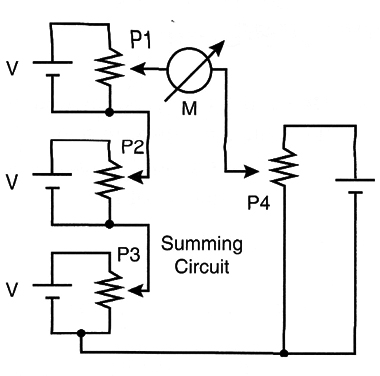
Figure 17 shows how a summing circuit can be added using two or three potentiometers wired in series. The voltage in A is the sum of the analog voltages set in potentiometers P1, P2, and P3.
At the school
The analog computer is a great tool for teaching and learning mathematics. The reader can make simple calculations, and the teacher can use the project in classes to show how slide rules and abaci operate. Crossover in the following areas is suggested:
Teaching mathematics
Knowing how potentiometers can be used to make calculations
Understanding how we can work with analog quantities to make calculations
Studying how logarithrns can make many types of calculations easier
More Circuits
The basic version is the simplest; we had no electronic active parts in the circuit, and only passive components as resistors and potentiometers.
Electronics can be used, and with sensitive circuits the computer becomes more precise and easier to use.
The reader may want to try the following versions.
Using a Sound Indicator
Instead of a visual indicator (instrument), you can use an auditory indicator (piezoelectric transducer).
The basic difference in the electronic circuitry is that the signal source will be an audio oscillator and the indicator will be a transducer. The basic circuit for this version is shown in Figure 18.
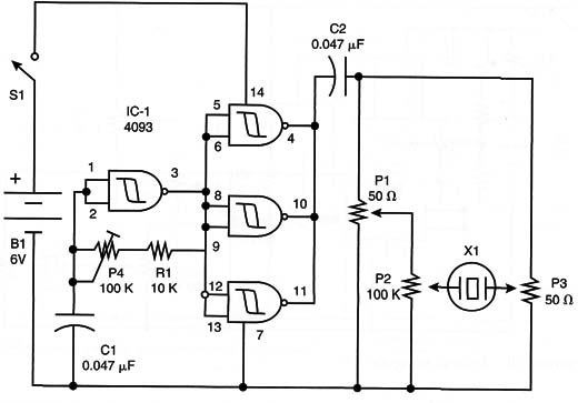
When the calculator completes an operation, the sound in the transducer disappears. The circuit can be mounted on a small printed circuit board (PCB), as is shown in Figure 19. Take care with the position of the IC. The tone is adjusted by P1.
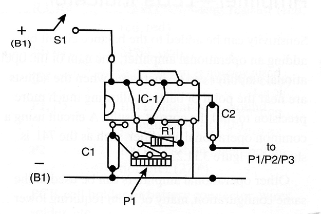
The oscillator is made from one of the four gates of a 4093 IC and pulls very little current, therefore extending the life of the battery. The three other gates are used as digital amplifiers. The transducer must be a piezoelectric high-impedance type. Low-impedance transducers won’t work in this circuit.
Using a Sound Indicator I
IC1 4093 complementary metal oxide semiconductor (CMOS) IC
R1 10 k ohm x 1/8-Watt resistor (brown, black, orange)
P1, P3 50 ohm linear wire-wound potentiometers (2700)
P2 100 k ohm linear carbon potentiometer (2700)
P4 100 k ohm trimmer potentiometer
C1, C2 0.047 ptF ceramic or polyester capacitor
S1 SPST switch
Xl1 Piezoelectric transducer
B1 6 volts of power (4 AA cells with holder)
PCB, wires, box, knobs, solder, etc.
Using 3 Sound Indicator II
Another circuit using sounds to detect the null point is shown in Figure 20.
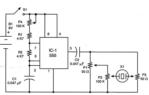
This circuit is based on the well-known 555 IC and is configured as a stable multivibrator, generating a square signal, with the frequency adjusted by P4. The circuit can be mounted using a small PCB, as shown in Figure .21.
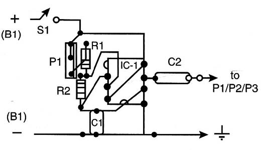
The operating principle is the same as in the previous project. The null detector is a piezoelectric transducer or a high-impedance transducer.
Parts List-Using 3 Sound Indicator II
IC-1 555 IC timer
P1, P3 50 ohm linear wire-wound potentiometer (2700)
P2 100 k ohm. linear carbon potentiometer (2700)
P4 100 k ohm trimmer potentiometer
R1, R2 4k7 ohmx 1/8-Watt resistor (yellow, violet, red)
C1, C2 0.047 up: ceramic or polyester capacitor
X1 Piezoelectric transducer
B1 6 volts of power (4 AA cells with holder)
PCB, wires, knobs for the potentiometers, solder, box, etc.
Adding an Operational - LEDs Indicator
Sensitivity can be added to the balance circuit by adding an operational amplifier. The gain of the operational amplifier can be increased when the adjusts are near the point of balance, allowing much more precision to find the correct results. A circuit using a common operational amplifier, such as the 741, is shown in Figure 22.
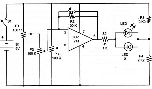
Other operational amplifiers can be used in the same configuration, many of them requiring lower voltages.
When the circuit is in use, the low-gain position is recommended. When the position corresponding to the mathematical result is almost found, the switch S2 is put in the position for high gain. This circuit can be used to detect two LEDs. When the balance is found, both LEDs will turn off.
LED Indicator - Operational Amplifier
IC-1 741 IC operational amplifier
LED1, LED2 Common LEDs (any color)
R1 1 k ohm x 1/8-watt resistor (brown, black, red)
R2 100 k ohm x 1/8-watt resistor (brown, black, yellow)
R3, R4 2.2 k ohm x 1/8-watt resistor (red, red, red)
S1, S2 SPST switch
B1 9 volts of power (6 AA cells)
P1, P3 100 ohmlinear Wire-wound potentiometer (2700)
P2 100 k ohm carbon linear potentiometer (2700)
PCB, cell holder or battery connector, wires, solder, etc.
An Advanced Circuit With Four Potentiometers
More complex calculations, including equations, can be solved with a four-potentiometer version of the analog computer. As shown in Figure 23, the circuit can solve equations of the following type:
A/B : C/D
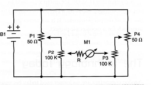
Using this circuit to solve an equation, any of the four potentiometers can be the x. For instance, in the equation 3x : 2 x 4, the potentiometers are adjusted in the following order:
Pl = 3
P3 = 2
P4 = 4
And you will move P2 (x) to balance the circuit and solve the equation.
An Automatic Mechatronic Analog Computer
Gearboxes and a comparator can be used in an advanced project of an analog computer, as Figure 24 shows.
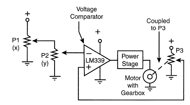
This circuit senses the voltage resulting from the operations of P1 and P2, and compares it with the voltage in the cursor of P3. If the voltages are not the same, the circuit acts and moves the cursor of P3 with a servo. The cursor will move until the voltages are the same.
A comparator (LM339, for instance) is used to sense the voltages and drive a DC motor coupled to the axis of the potentiometer. It is an interesting approach for a mecatronic project.


