

For the datasheet of the 4017 type CD4017 click here.
There isn’t a limit to what can be made with the 4017 integrated circuit. We can make it count to any number between 2 and 9 and cascading several of them it can go beyond. We can use it for timing, encoding, to generate waveforms, light and sound effects and much more.
All this justifies the frequency which the reader finds projects that are based on this integrated circuit. Using the 4017 circuit is simple and once the reader masters this technique, the reader will be able to make his/her own designs using this component. Thus, in the following lines we will show how the 4017 works and how we can use it in several ways.
The Integrated Circuit 4017
The integrated circuit 4017 belongs to the CMOS logic family in which the components may operate with voltages from 3 to 15 volts and have characteristics that allow its direct interconnection and with other components such as the 555. In the 4017 we found a Johnson counter/decoder with an input and 10 outputs, as shown in the block diagram of figure 1.
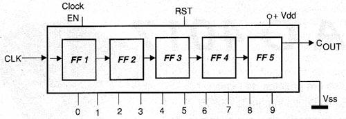
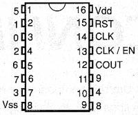
As it can be seen, it consists of 5 steps that can make the division of a rectangular signal by values ??between 2 and 9. The 4017 is provided in a DIL package of 16 pins with the terminal arrangement shown in figure 2.
In the normal operation, the pins 13 and 15 are grounded and rectangular pulses are applied to the input pin (14). As we can see in the time diagram shown in figure 3, starting from the condition in which the S0 output is found at the high level and the others at the low level, the following occurs: each pulse applied, the output which is at the high level passes to the low level and the next goes to the high level.
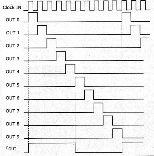
The process occurs until it gets to the last output. With a new pulse, this output goes to the low level and the first goes to the high level, starting all over again.
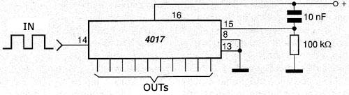
We reset the 4017 count taking the pin 13 for a moment to the high level. One way to make the 4017 always starts from zero, with the first output at the top level, is with a circuit "reset while turning it on" as shown in figure 4. This circuit is also called POR (Power-On Reset).
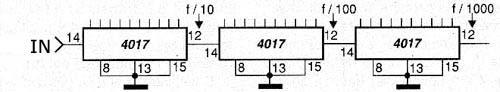
The integrated circuit 4017 may be cascaded in order to obtain the division by 10,100, 1000, etc., as shown in figure 5.
But, we can program the 4017 to make count lower than 10. To do this, simply connect the pin immediately after the number we want to count to the reset input, as shown in figure 6.
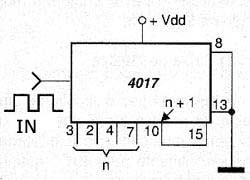
For example, if we want to count until 4, with the activation of 4 outputs in sequence, just turn on the fifth output to reset the pin. If we want to count until n (n smaller than 10) simply plug the pin after n to the reset (15).
Electrical Characteristics
The electrical characteristics are given in the following table:
Supply voltage range
| Characteristic | Conditions (Vcc) | Value | Uniys |
| Drained/supplied - Current (tip) | 5 V 10 V 15 V |
0.88 2.25 8.8 |
mA mA mA |
| Maximum frequency of clock (tip) | 5 V 10 V 15 V |
2 5 6 |
MHz MHz MHz |
| quiescent current (max) | 5 V 10 V 15 V |
0.3 0.5 1.0 |
mA mA mA |
| 3 a 15 | V |
As we can see, the type of output used in this integrated circuit allows it to have the same ability to drain or supply current to a load. As in normal applications, the maximum current it can provide is small and we often make use of power steps to excite loads of higher consumption.
In figure 7 we have some kinds of power stages that can be used with the 4017.
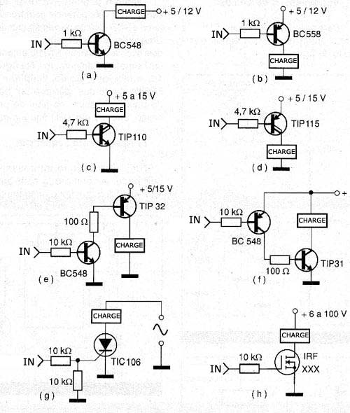
In (a) we have the excitment at the high level with a NPN transistor for loads up to 100 mA. To the excitement at the lower level, we have the circuit with PNP transistor shown in (b).
Wishing to excite higher power loads there is in (c) a version that uses a Darlington NPN transistor. This version is excited with the output at the high level. To excite loads at the lower level, we have the use of a Darlington PNP, as shown in (d). In (e) there is the possibility to use a complementary pair of common transistors to excite loads with high currents at the high level.
The equivalent configuration to excite the low level is shown in the figure (f). We can also excite SCRs (g) and power MOSFETs as shown in the same figure in (h). To excite the input of a 4017 there is also various possibilities shown in figure 8.
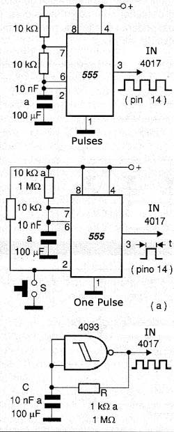
The first makes use of the known integrated circuit 555 which is fully compatible with the 4017, as we can see. The second uses an oscillator or other gate circuit with the integrated circuit 4093. Other functions CMOS can be used for the same purpose. When the 4017 is excited, however we must bear in mind that the signal should be perfectly rectangular free of bouce (oscillations) that can distort the count.
Applications:
Following there are some practical circuits based on the 4017.
a) 10 LEDs Sequential
In Figure 9 we have a sequential circuit that triggers 10 LEDs at a speed that can be adjusted in the potentiometer P1 and basically depends on the capacitor C1.
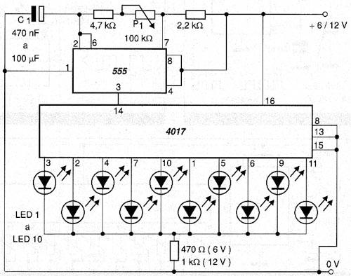
The resistors to the cathodes of all LEDs are designed to limit the current in the circuit. To trigger the power loads we can interface with transistors or SCRs, as shown in figure 10.
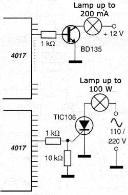
Note that in the case of SCRs they have a common ground to the high and low voltage circuit. This is absolutely necessary for shooting. One possibility being considered to excite loads of high power with transistors is the use of Darlingtons. In the case of TIP121, which would replace the BD135 we can increase the base resistor from 1k to 4k7.
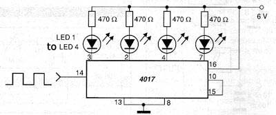
b) 4 LEDs Sequential
Triggering 4 LEDs in a sequential system we have the circuit of figure 11.
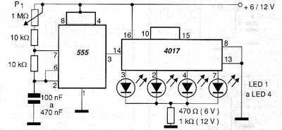
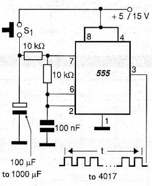
We can also trigger loads of greater power with transistors and SCRs like the previous version. An interesting variation of the two circuits is to make a "sorter" of numbers. In figure 12 we show how to enable the 555 so that it generates a pulse train and then, at the end of the process, only one LED is lit.
c) Sequential Switching Off
Another interesting circuit that can be elaborated based on the 4017 is he one that makes the LEDs sequential switch off and is shown in figure 13.
d) Music Box
Figure 14 shows a circuit of an electronic music box in which 10 musical notes are executed sequentially by the 4017 when the 555 is enabled.
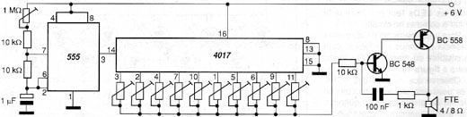
The note programming is made on the trimpots with the outputs of the 4017. The central note will depend on the oscillator capacitor with two transistors, which can be changed in a wide range of values.
The speed at which the notes are executed is set in the 555 trimpot.
e) Programmable Logic Control (PLC)
The automation of small devices can be implemented based on a 4017 with the circuit of figure 15.
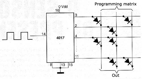
In this circuit, when an output goes to the high level, if there is a diode connected to this output, in the control matrix, it activates the corresponding output.
Combining diodes we can make the outputs achieve different sequential trigger levels, finally controlling an external automation system. The sequence and what will be triggered only depends on the reader's imagination: opening a door, turning on the lights for a slightly longer period of time, in the end of the process ringing a bell and then closing the door again is an example of application that can be done by the programming matrix shown in figure 16.
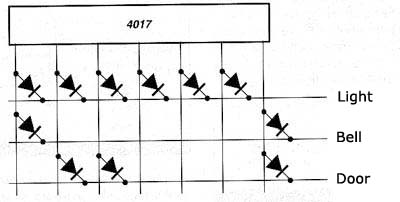
The total duration of the cycle will only depend on the P1 setting the oscillator with the 555 which is responsible for the triggering.
f) Waveform Synthesizer
We finished our series of practical circuits with a waveform synthesizer that can be used in musical instruments and effect generators. The frequency of the output signal of the circuit of figure 17 is the oscillator frequency with the 555 divided by 10.
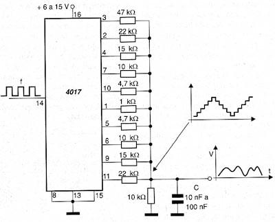
The output of RC filter flattens the signal in a way to obtain a smooth waveform.
Conclusion
The applications that we saw for the 4017 are just some of the thousands we have already published and seen in other articles in this site. Starting from the characteristics of this component there is no limit to what the reader can do.


