

Obtaining electricity from mechanical energy, as it is in a moving motor, is relatively simple. The first vehicles with explosion engine have already used the dynamos in order to obtain electric power for the battery and thus to the spark plug, essential to the ignition system. It was a simple system in which a dynamo was driven by the engine, generating a low DC voltage and passing a voltage regulator system fed electric car devices which besides the ignition system included headlights, also charging the battery with the excess power.
So as shown in the simple diagram of figure 1, the purpose of the dynamo would be to supply power to the electrical system with the car moving. For the ignition and eventually to turn on the lights with the car stopped, should the battery be of use.
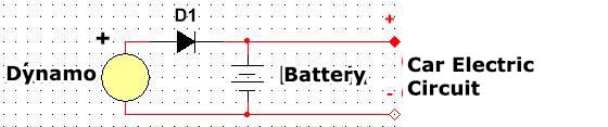
The major disadvantage of the dynamo is that it requires a minimum engine speed of motor rotation so that it produces enough voltage to power the circuits, hence the need for a voltage regulator system that kicks in when the voltage reaches the minimum required.
For vehicles that travel in the city and therefore are subject to consequential stoppages or low speed with reduced engine speed, the use of dynamo has serious drawbacks because there is the danger of it to not provide by the necessary time the energy to charge the battery.
Generating alternate voltages and with the use of semiconductor diodes and even electronic circuits it is possible to obtain a much better performance for the electrical system of the vehicle and this is what happens in modern vehicles that use only the alternator solution as a source of energy from the motor. Only in the simplest vehicle electrical systems we find the same configuration that makes use of the dynamo, such as on bicycles to light a beacon or signal lights.
In modern automotive vehicles that are more sophisticated the electronic appears in almost every function of this circuit and even in additional functions to improve performance.
The alternator which is the starting point of this system is an electro-mechanical device and as such, besides the wear of the moving parts it may be defective. The presence in current models of some internal electronic devices of this device makes a lot of car electricians have certain fear in handling, but with the explanations that follow, readers will see that this is not justified.
THE DYNAMO AND THE ALTERNATOR
The operating principle of a dynamo is very simple: if we have a coil which rotates within a magnetic field created by a set of magnets or other coils, as shown in figure 2, each time the windings of this coil cut the magnetic field lines it appears an electrical voltage in the coil ends.
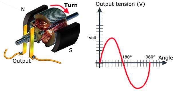
Turning on a lamp or another device capable of converting electrical energy into another form of energy, it will work: in the lamp case it will light. This indicates that, to cut the magnetic field lines of force it is necessary to make a mechanical stress in the coil, and the mechanical energy required is converted into electrical energy. The problem of the device we see is that for each half turn the coil gives within the magnetic field it cuts twice its power lines, and this happens on opposite directions.
This means that for each turn, cutting the lines twice on opposite directions, the coil generates a tension now with the positive on one side, then on the other. In other words, spinning in these conditions, we produce an alternating current.
In order to correct this problem, in the coil output we binds a brush system, as shown in figure 3, which inverts one of the poles on one of the half turns, so that we have the current always flowing on the same direction, that is to say, to obtain a direct current.
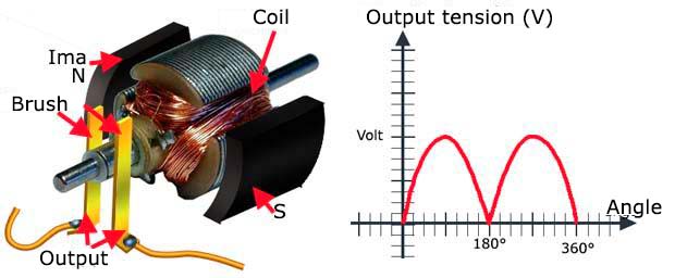
This leads to the so-called dynamos devices. If we eliminate the system which reverses the current direction to every half-turn of the windings, the device starts to generate alternate current, i.e. we will have an alternator. In the past it was not easy to convert the alternate current in the direct current needed to many electrical and electronic devices of a car and so the use of Dynamos was compulsory. However, the availability of silicon diodes we can easily convert alternate currents into direct ones, so that it doesn’t matter for an electrical circuit if it has as a power supply with either direct or alternate voltage.
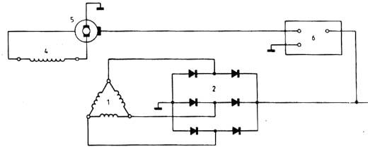
Thus, in modern vehicles, instead of using dynamos we have alternators, in other words, similar devices that have a set of movable coils which rotates within the magnetic field of a fixed set of coils, as shown in figure 4.
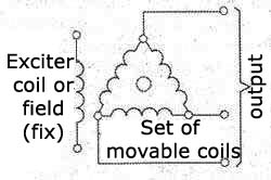
In this case, as the polarity of the current is reversed continuously, i.e. the poles alternate, we have an alternator. Diodes are added to the device itself in a way to obtain the direct current the electric car circuit needs to function.
In figure 5 we have the arrangement of the diodes showing that to facilitate the production of energy in a more constant way we use three sets of coils and therefore three sets (pairs) of diodes in most circuits.
The operation of an alternator in a vehicle, however, does not show linearity, what is not interesting to the electric circuit of a car. The several devices that are powered by electricity in the car require a fixed voltage, or at least that oscillates inside a narrow range. Very large tension variations can cause damage to many of these devices.
We know the voltage that a dynamo has at its output, as shown in figure 6, depends on many factors like the speed at which the engine rotates and the current intensity required by the circuits connected to it.
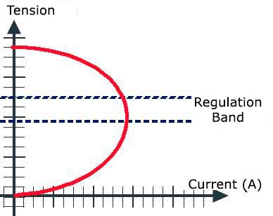
The biggest problem is the enormous speed range of variation of a car engine that can have speeds between 500 and 6000 rpm. For the car electrical circuit to be powered by a voltage within a safe range, there must be added voltage regulators devices.
THE ALTERNATOR ON THE INSIDE
In figure 7 we have an exploded view of a typical car alternator showing its various parts.
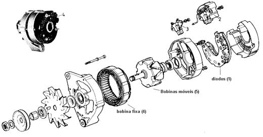
Internally we observe two sets of windings: the field windings that generate the magnetic field that the windings of the other winding must and the stator winding which generates energy. Internally we have a board in which six power diodes are installed to rectify the alternating current generated. These diodes are fixed on a single piece of metal which also serves as a heat sink (1 in figure 7).
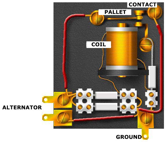
The voltage regulation in older vehicles was made by an electro-mechanical device like the cars that used dynamos as shown in figure 8.
In modern vehicles, however, voltage regulators are used with power transistors in settings as shown in figure 9.
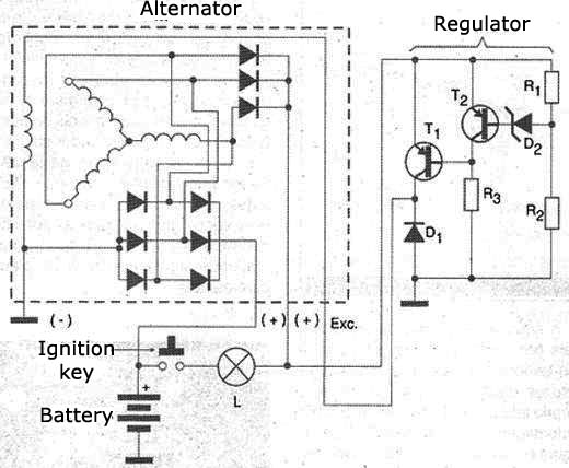
We usually have the traditional configuration of the series regulator in which a power transistor works as either a rheostat or a variable resistor dosing the excitation current of the excitation winding in order to control the intensity of the magnetic field whose mobile winding turns will cut.
This process is much better than if we try to control the main current generated by the dynamo that is into tens of amperes thus requiring very high power transistors. Even so, the transistor used must be the type of high-current (20 A or more) since this is the order of magnitude of the generated current.
The reference voltage for the output can be given by the zener diodes as integrated circuits. In the circuit shown as an example, the zener diode Z2 sets the voltage to the transistor T2 which functions as a driver, controlling the main current through the transistor T1. In figure 10 there are currents in this circuit during operation.
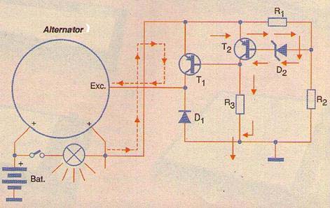
Note that this circuit there is a panel indicator lamp connected which goes out when the generated voltage is applied to the circuit that occurs when the motor starts. More complex configurations may have up to 5 transistors, also found in some vehicles. Figure 11 shows a configuration in which we have a regulator controlled by a SCR.
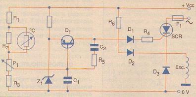
In this circuit the SCR firing point after switching is determined by the voltage generated, running as well as a phase control. It is important to note that the use of delicate electronic equipment in the car, especially microcontrollers circuits that do all the control of the electrical system and the engine do not admit large variations in the supply voltage and there can be easily damage hence the need for precise regulatory and efficient circuits.
SERVICE
For electronic technician or car electrician, the presence of an electronic circuit that is normally embedded in the installation and often protected by means preventing access to its components is difficult when doing a test run and possibly repairing. Therefore, finding that the problem is the voltage regulator or the alternator diodes sets, the most common procedure is to exchange the full set.
However, many times the access to a relatively simple circuit can reveal to us that only a low-cost component must be replaced and this may mean some savings and an alternative solution when the full original part is not available.
Many regulators have an adjustable point which is a variable resistor; (Trimpot) which can be accessed by a screwdriver that allows making the circuit provide the output voltage according to the current.
The operating test of a regulator can be made by connecting the alternator output to a voltmeter, battery and an adjustable power supply from 0 to 15V and a lamp. Starting from zero voltage in the circuit when it reaches somewhere around 4 to 5 volts the lamp should light some brightness, but indicating that there is no current flow. Passing this tension to something around 14V lamp brightness should increase. This voltage will be indicated by the voltmeter connected in the indicated position of the circuit.
If the light goes off before reaching the 14 or 14.3V means that there may be a regulator malfunction or it is not properly adjusted. Try to adjust the regulator (if it has an adjustable point) so the lamp turns off with a voltage of 14.3V. For the second stage of the test adjust the output of the source to a 15V voltage.
With that the lamp should be off. Now gradually decreasing the output voltage should occur the lamp lighting with a voltage between 13.9 and 14V.
If it doesn’t happen we should redo the adjustment and repeat the first part of the test. With the procedure repeated a few times it is possible to take the regulator to the ideal point operation. Once the operation is tested the technician can reinstall the regulator or if necessary make the diagnosis to identify any components by the abnormal operation.


