This artcile was originally published by the author in Portuguese and translated to English to be part of one of his books.
A relay is basically formed by a coil and one or more pair of contacts as shown in figure 1.
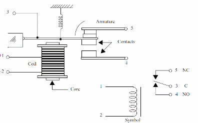
When a Voltage is applied to the coil the current ñow creates a magnetic field that attracts the contacts and closes the switch.
If the current across the coil is cut, the magnetic field disappears, and the contacts open.
An external circuit controlled by the Contacts can be triggered on and off by the current passing across the coil.
Two irnportant properties can be noted in this arrangement:
1. The controlled circuit is completely isolated frorn the control circuit.
2. We can apply low Voltage and low current to the relay’s coil to control high-Voltage and/or high-current circuits.
Relays come in different sizes and with various electrical characteristics as needed for a particular application.
The rnain characteristics we must consider when using relays are as follows:
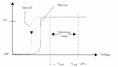
1. The nominal Voltage or coil Voltage (Vcoil). This is the Voltage that is applied to the coil to rnake the contacts close. In practice, the relay can close its contacts with voltages lower than indicated, and keep thern closed even when the Voltage falls below the norninal Value, as a result of the Characteristic of hysferesis. Types with voltages ratings between 3 and 48 V are comm in more part of the as Figure 2 illustrates.
2. The coil current (Icoil). This is the current that flows across the coil when the norninal Voltage is applied. Currents between 20 and 100 rnA are cornrnon in relays.
3. The coil resistance (Rcoil). This resistance can be found easily by dividing the nominal Voltage by the coil current. Values between 50 and 500 Ω are common.
4. Contact current (Icontact). This is the rnaxirnurn current that can be controlled by a relay. Typical values are in the range frorn 1 to 10 A.
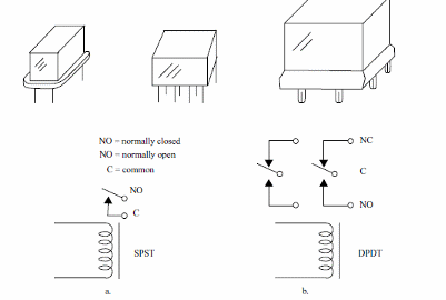
5. Type chontacfs. The relays are not rnerely sirnple switches controlled by currents. One coil can control one or rnore contacts in different configurations, as shown in Fig. 3. This figure also shows the symbol and the appearance of common relays. In Fig.3a, we have a single-pole, single-throw (SPST) relay, and in Fig. 3b a DPDT relay. Other types with multiple contacts can be obtained. Therefore, relays can act as SPST, DPDT, or multiple-contact/throw switches.
With the following formulas, you can compute any third characteristic of a relay when the other two are known:
Formulas:
1. Resistance of the coil when voltage and current are known,
R = V/I
2. Current in the coil when resistance and voltage are known,
I = V/R
3. Voltage in the coil when current and resistance are known,
V = R x I
In some cases, it is important to know the power dissipated by a relay in an applica-
tion. The following formula can be used for this task:
Formula:
7 ’3
P = V>
where P = power dissipated by the relay coil (W)
V= applied voltage (V)
I = current through the coil (A)
R = resistance of the coil (9)
SPECIALTYPES OF RELAYS
Latch Relays
Latches or bistable relays are turned on by a current flowing in one direction, and they maintain the “on” state even when the current is cut. To turn off the relay (or to bring it back to the previous state), it is necessary to apply another current to the coil-but in the opposite direction. Some latch relays use two coils-one to turn on and the other to turn off.
Solid State Relays
These are special types in which the contacts are replaced by some kind of solid state switch such as a transistor, SCR, TRIAC, or other device. More information about these devices can be found in the site.
Reed Relays
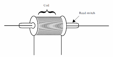
These are relays formed by a reed switch and a coil in the configuration shown in Fig.4. The operating principle is the same as with common relays: when a current flows through the coil, the resulting magnetic field acts on the contacts of the reed switch and closes them. Reed relays are small and very sensitive but can’t handle large currents. Normally, they are used to control currents up to several hundred milliamperes.
HOW RELAYS ARE USED
When using a relay, we have to consider both the device that is to be controlled (wired to the contacts) and the circuit that will drive the relay.
USING THE CONTACTS
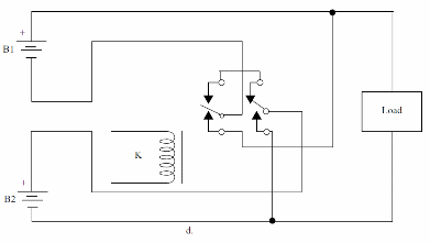
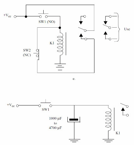
Figure 5 shows how relay contacts are configured. In this figure, we show several applications as described below:
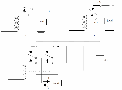
a. In Fig. 5a, we show the simplest application ofthe relay. It is used as an SPST switch to control an external load. The load is on when current flows across the coil.
b. In Fig.5b, we show how the normally closed (NC) contacts can be used to turn a load off when the relay is energized. This configuration is preferred when the loads on time exceeds the offtime.
c. Figure 5c shows how a DPDT relay can be used to control the direction of the current flowing across a load. When the relay is off, the direction of the current is I1 When the relay is on, the direction is I2.
d. In Fig. 5d, a relay is used to switch power supplies or loads, changing from series to parallel and vice versa.
e. Another interesting application is shown in Fig. 5e. When SW1 is pressed, one pair ofcontacts is used to latch the relay. To turn offthe relay, we momentarily press SW2. Notice that SW1 is a momentary, normally open switch, and SW2 is a momentary, normally closed switch.
f. As shown in Fig. 5f, by momentarily pressing SW1, the relay closes the contacts and remains in this state for an interval that is determined by the value of the capacitor and the resistance ofits coil. A sensor can be used as SW1.


