Researchers discovered that any semiconductor diode produces infrared light when conducting a current, the beginning of the LED’s principle of operation.
Advancing with the research, they found that special semiconductor materials, such as gallium when doped with special impurities like those of arsenium and indium, could result in diodes that emitted visible light when forward-biased.
From this appeared a new class of diodes-the LEDs-that were primarily designed to act as light sources or infrared sources.
LEDs are monochromatic light sources because the light produced in their junction has a narrow spectral band as shown by the graphics in Figure 1.
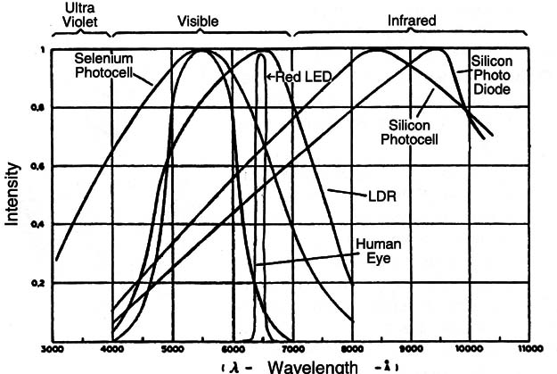
LEDs are made of materials such as Gallium Arsenide (GaAs) doped with impurities like indium or phosphorus, in a degree that gives them their light emission characteristics or other spectral characteristics.
The impuri- ties also determine the minimum voltage for forward-biasing an LED that makes it conductive. Red LEDs become conductive with 1.6 V; yellow LEDs need about 1.8 V, and blue and green LEDs need more than 2.0 volts.
Symbol and View
Figure 2 shows the symbol used to represent LEDs in schematic diagrams and in the same figure is the main type of LED.
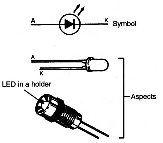
The different types and LED inaholder sizes depend on the color of the light and also the application. IR (Infrared) LEDs are used in remote controls and as sensors. LEDs can also be placed to form an eight in seven-segment display
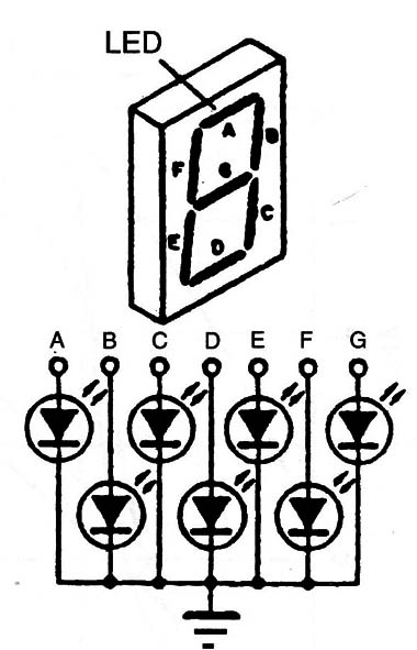
Each segment in LED this kind of display is an LED. Figure 3 shows how they are connected.
If all the LEDs are wired with the cathodes together they are called common-cathode displays.
It is also possibleto make a white LED by putting three LEDs on a chip with the basic colors (Red-Blue-Green or RGB) and powering them in a way that the combination of their light results in white.
According to the amount of current in each of these LEDs, it is also possible to produce any color of the visible spectrum.
The LEDs, like the diodes, are polarized components.
Normally they are encapsulated in clear or colored plastic with a small, flat space or notch near the cathode lead.
Specifications
LEDs are specified by a part number provided by the manufacturer.
But, catalogs also indicate other characteristics including the size, forward-bias voltage, maximum current, and the wavelength or color of the produced light.
a) Current: The amount of current flowing through an LED determines how much light or IR it can produce. Typical values are between 5 and 100 mA. This current is important to help the designer calculate the current limiting resistor (see how to use an LED).
b) The fonNard voltage: This is the voltage at which the LED becomes a conductor. It is the minimum voltage that can be applied to the LED in a circuit.
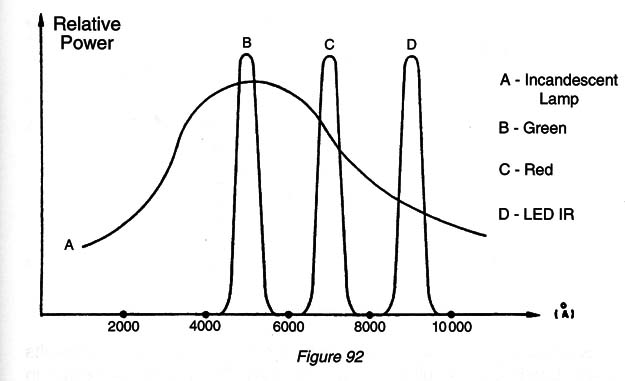
c) Wavelength of the light: The wavelength can be expressed in angstroms (A) or nanometers (nm). 1000 A = 100 nm. The visible spectrum extends from about 4000 to 7000 angstroms or 400 to 700 nm. Figure 4 shows the placement of the emission curve of some common LEDs according to their colors.
Where they are found and used The main applications of LEDs in electronic equipment are as indicators.
The electrician will find LEDs in panels of electronic, and even electric, devices indicating a function or displaying a number or even a figure as in the seven-segment types.
The seven-segment displays also indicate the result of operations in calculators, the hours and minutes in clocks, time, and other information in microwave ovens, etc.
Infrared LEDs are found in remote controls of a variety of equipment like TVs, VCRs, automatic doors, car alarms, etc.
Now LED-lamps are becoming commun since they best performance, draining less power.
When using LEDs it is important not to exceed the maximum allowable forward current.
Current is best limited by a resistor placed in series with the LED and the power supply as shown in Figure 5.
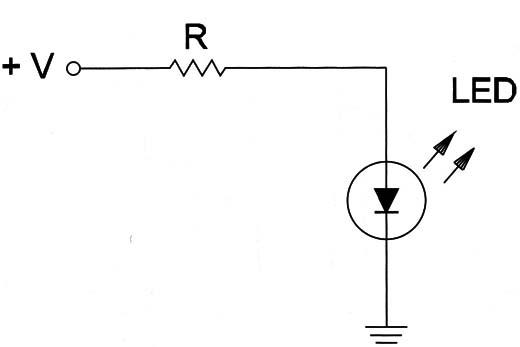
The resistances of the series resistor can be calculated by subtracting the LED’s forward voltage from the power supply voltage and dividing the result by the desired current in amperes.
For example, if we want to power a red LED at 20 mA from a 6 V power supply the math is as follows:
Subtracting 1.6 V (the forward voltage of a red LED) from 6 V results in 4.4 V.
Dividing the result (4.4 V) by the current 20 mA (0.02 A) results in 220 Ω.
Testing
Never test an LED by plugging it into a power supply without a series current-limiting resistor. It can be burned.
The best way to test is by plugging it into a 3 V supply (2 AA cells) in series with a 100 Ω to 270 Ω resistor as shown in Figure 6.
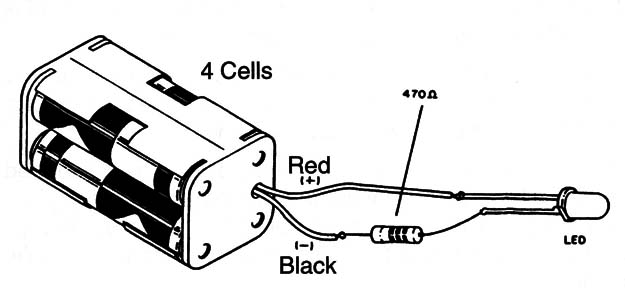
The LED will glow if it is good. To check whether an infrared LED is producing radiation, some kind of detector must be used.


