

Note: this article was originally published in a Brazilian magazine and them transleted into English by the author to be part of one of his books.
As shown by the structure in Figure 1, an N-type silicon bar forms the UJT where two terminals called base 1 and base 2 (B1 and 82) are placed. Between these terminals the device presents an ohmic resistance.

A PN junction is formed in the middle of the N-region where an emitter terminal is placed. In a typical circuit, such as an oscillator, the device is biased as shown in Figure 2.

The N-material placed at the middle of the bar acts as a voltage divider placing a certain voltage in the emitter region.
The capacitor placed at the emitter of the transistor charges until the voltage between its plates rises to the value of the emitter voltage plus about 0.6 volts.
When this voltage is reached the device turns on and the resistance between the emitter to Base 1 falls to a very low value.
The capacitor can then discharge through this circuit. A high current pulse is produced in this process.
As long as the charge in the capacitor is reduced, and the voltage across it falls to an appropriated value, the transistor turns off and returns to the nonconductive state.
The charging process of the capacitor starts again and a new oscillation cycle begins.
Figure 3 shows the waveforms of the signals produced by this circuit.

We can consider this the solid-state equivalent of the previously described relaxation oscillator using a neon lamp.
The UJT is a low-frequency device and signals of no more than some hundreds kilohertz can be produced by this basic configuration.
Symbol and Diagram
Figure 4 shows the symbol used to represent a UJT. In the same figure is a diagram, (b).

One of the most popular UJT transistors, found inprojects published by electronics magazines and even in some kits and appliances, is the 2N2646.
Specifications
As in any other transistor, there is a part number figured on the device’s body for its identification.
But, when building a project and trying to understand how the circuit works or looking for a replacement type, it is important to know some electrical specifications of a UJT.
The most important are listed here.
a) Voltage between bases (Vbb)-the maximum voltage that can be applied between bases. For the 2N2646 the specified value is 35 V.
b) Voltage between emitter and base 1 (Vb1e)-the highest voltage that can be applied between the two indicated electrodes. For the 2N2646 the value is 30 V.
c) Intrinsic standoff ratio (17 )-the position of the emitter junction referring to the bases. This value is used to calculate the trigger point as a function of the applied voltages. For the 2N2646 this value is in the range between 0,56 and 0,75.
d) Resistance between bases (Rbb)-the ohmic resistance that can be measured between bases. Typical values for the 2N2646 are in the range between 4.7 and 9.1 k Ω.
e) Peak Pulse Emitter Current (le)-the maximum current that can flow between emitter and Base 1 when the transistor is triggered.
Where they are found The UJT isn’t a modern device-it was introduced on the market around 1960.
Today equivalent circuits using modern devices are used to perform the same functions of a UJT.
They are still found in many electronic and electric applications depending on the date they were made or their purpose.
The basic configuration of a UJT is as a relaxation oscillator.
This type of circuit is found in timers, alarms, motor controls, toys, and others.
For the reader, it is important to know that the frequency of the signal produced by the UJT depends on R and C and can be calculated with a certain degree of precision by the formula:
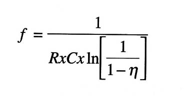
Where
f is the frequency in Hertz (Hz)
R is the resistance in Ω (Q)
C is the capacitance in Farads (F)
ln is the natural logarithm
? is the intrinsic standoff ratio (about 0.6 for the 2N2646)
How to test
Using a multimeter you can make two tests in a UJT:
1. The resistance between the two bases in any direction is between 4.5 and 12 k Ω for a common UJT.
2. Placing the probes between the emitter and Base1, a high resistance can be measured in one direction and a low resistance in the opposite direction. This means that the junction (acting as a diode) is good.
The best way to test this device, however, is to mount a simple probe circuit like the one shown in Figure 5.

If the transistor is OK the LED will flash at a rate that can be adjusted by the potentiometer.


