Eduardo de Pinho Prado, Prof. Edu from Colégio Mater Amabilis – Guarulhos – SP - Brazil, teaches physics and contributes to this site.
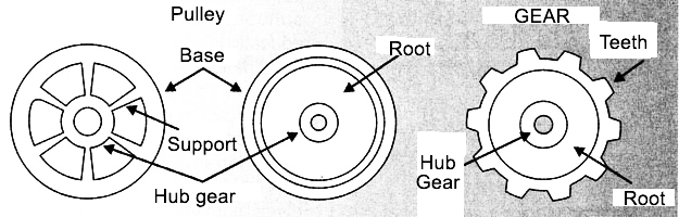
The pulleys and gears are wheels used in the transmission of the circular motion. They consist of a crown, in wheel hub and in sets of arms or disks, whose function is to rigidly connect the crown to the wheel hub. Figure 1 shows some representations of pulleys and gears.
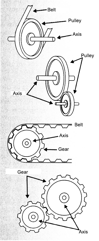
Placed in a mechanism, these wheels transmit a circular motion through a belt or direct contact between crowns while their hubs are coupled to axles (Figure 2).
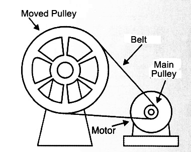
When transmitting the circular motion using a pair of wheels, the wheel which originates the motion is called the driving wheel, while we call driven wheel the one that captures this motion. Normally the driving wheel has its hub connected to the shaft of an engine (Figure 3).
UNIFORM CIRCULAR MOTION (U.C.M.)
To better understand how is the transmission of the circular motion in the coupling of pulleys or gears, it is necessary to review some physical concepts.
Consider a particle moving in a circular path of radius r, with a constant v scalar speed (U.C.M.). The time required to complete one revolution is constant and called rotation period (T). (Figure 4)
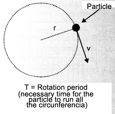
For this movement we call frequency (f) the number of revolutions performed in a certain unit of time. The usual frequency units are Hz (hertz) which means "revolutions per second" and RPM meaning "revolutions per minute".
There after there are some relations between the magnitudes involved in the study of uniform circular motion:
f = 1 / T
v = 2πr / T
v = 2πrf
U.C.M. TRANSMISSION
By coupling pulleys the main goal is to obtain a frequency of rotation in the driven pulley different from the one obtained by the driving pulley.
For couplings by belt or contact, the scalar speeds of the crowns of the associated wheels are equal. In the case of the coupling by belt the scalar speeds of the crowns correspond to the own speed of the belt (Figure 5).
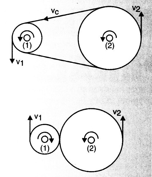
V1 = V2 = Vc
V1: scalar speed in the wheel crown (1);
V2: scalar speed in the wheel crown (2);
Vc: scalar speed on the belt.
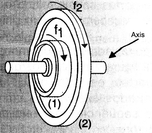
Consider the two-wheel coupling (1) and (2) of equal respective radius r1 and r2. The wheel (1) rotates with frequency f1.
We can determine the rotation frequency f2 of the wheel (2) from the equality of scalar speeds of these wheels crowns (Figure 6).
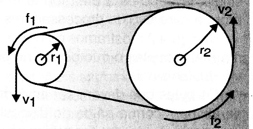
v1 = v2
2πr1f1 = 2πr2f2
f2 = f1 ( r1 / r)
As the diameter of a circle is twice its radius, the relation between the rotational frequencies f1 and f2 can be given by:
f2 = f1 (D1 / D 2)
D1 = diameter of the wheel (1);
D2 = diameter of the wheel (2).
Now consider two gears (1) and (2) where n1 and n2 are the amounts of teeth in these crown gears. If T1 and T2 are the periods of route rotation (1) and (2) the scalar speeds v1 and v2 of their crowns can be given by:
v1 = n1/T1
or
v2 = n2/T2
with v1 and v2 measures, for example, in "teeth/s" or "teeth/min"
v1 = v2
n1/T1 = n2/T2
n1f1 = n2f2
fn2 = f1(n1/n2)
Equating these scalar speeds we have:
There is a further possibility of coupling, which consists of building two wheels on the same axis of rotation. In this case the rotational frequencies are the same.
f1 = f2