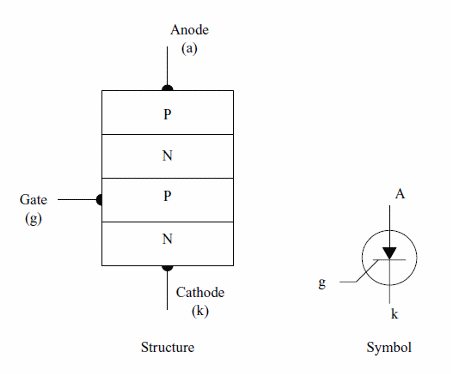
The SCR or Silicon Controlled Rectifier is a four layer device of the thyristor family. The the symbol, structure and equivalent circuit are shown by figure 1.

The SCR, as the symbol suggests, can be compared to a diode that conduces the current in only one direction once triggered.
To trigger on a SCR is necessary to apply a positive voltage to the gate. This voltage biases the NPN transistor of the equivalent circuit to the saturated state. This cause a feedback that makes the PNP transistor to go to the saturated state too.
Even when the trigger voltage disappears, the transistors remain on due the feedback. To turn off the SCR there are two possibilities to consider:
a) Put in short by a switch the anode and the catode making the voltage between these elements fall to zero. Pressing the switch by a moment, the SCRs turns off.
b) Turning off the power of the circuit. When the power is turned on again the SCR remains off if no trigger voltage exists in the gate.
Common SCRs are very sensitive and can be triggered by currents as low as few hundreds microamperes as the TIC106, MCR106, IR106, etc. The trigger voltage for those devices are in the range between 1 and 2 Volts.
The main current, between anode and cathode are typically in the range from 100 mA to more than 100 A.
Specifications
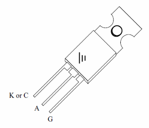
The SCRs are identificated by a part number given by the manufacturer and figured in the own package. From this part number, looking in a handbook, databook or data sheet is possible to know the electrical characteristics.
When using any SCR is important to know the next characteristics:
a) Maximum voltage between anode and cathode
It is the maximum voltage that can be applied to the SCR when it is in the off state. Typical values range from 50 to more than 1,000 volts for common types. This specification can also be indicated as Repetitive Peak Off voltage and abreviated by Vdrm or as Repetitive Peak Reverse Voltage and abreviated by Vrrm.
b) Maximum current
This is the maximum current that the SCR can hold when in the conductive state. Common SCRs, found by the electrician in appliances connected to the AC power line, are specified to control currents in the range from fraction of ampere to more than 50 amperes.
c) Dissipation power
When a SCR is on, independently of the current it is conducing, the voltage between anode and cathode is about 2 volts. The product of this voltage by the current gives the dissipation of the SCR. The maximum dissipation of a SCR is important to calculate the size and shape of the heatsink.
d) Holding current
It is the lowest current that the SCR can conduce without turn off. This current is abreviated by IH.
Other important specifications are the speed of the device given by a value named "Critical Rate of Rise of Off State Voltage" and measured in volts by microsconds. This value says how fast the voltage applied to the load increases when the SCR is turned on.
How to Use
The SCRs can be used both in AC and DC circuits. In DC circuit we only must remember that the device remains on after the trigger signal is removed.
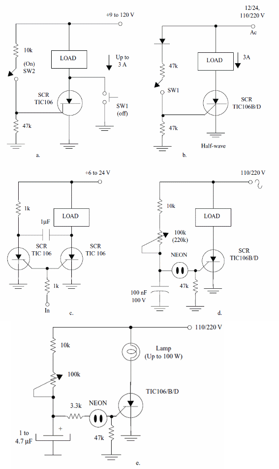
Figure 2 shows some practical circuits using SCRs.

a) Power switch - DC - SW1 is pressed to turn off the circuit
b) Power Switch - AC
c) Flip-Flop Using SCR
d) AC dimmer
e) AC Flasher
When a SCR is on, to keep it on a minimum amount of current must be passing accross. This current is called "holding current" and is in the range of some miliamperes for common devices.
Another important point to be considered when using SCRs in low voltage circuit is that a voltage fall about 2 V is produced when it is on.
In some apllications in robotics and mechatronics this voltage fall must be compensated by an increasing of the power supply voltage. In high voltage applications (plugged to the AC power line, for instance) this voltage fall can be disconsidered. This voltage also determine the amount of power converted in heat by the device when in operation.
Formula:
Heat dissipated in an SCR:
Pd = V x I
Where:
Pd is dissipated (W)
V is the voltage fall accross the SCR - typically 2 V
I is the current accross the SCR (A)
How to test
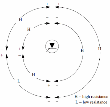
A simple test using the multimeter is shown by figure 3.

Common SCRs - Table
| It (A) | Vdrm (V) | Igt(max) (mA) | |
| TIC106Y | 5 | 30 | 0.2 |
| TIC106F | 5 | 50 | 0.2 |
| TIC106A | 5 | 100 | 0.2 |
| TIC106B | 5 | 200 | 0.2 |
| TIC106C | 5 | 300 | 0.2 |
| TIC106D | 5 | 400 | 0.2 |
| TIC116F | 8 | 50 | 20 |
| TIC116A | 8 | 100 | 20 |
| TIC116B | 8 | 200 | 20 |
| TIC116C | 8 | 300 | 20 |
| TIC116D | 8 | 400 | 20 |
| TIC116E | 8 | 500 | 20 |
| TIC116M | 8 | 600 | 20 |
| TIC126F | 12 | 50 | 20 |
| TIC126A | 12 | 100 | 20 |
| TIC126B | 12 | 200 | 20 |
| TIC126C | 12 | 300 | 20 |
| TIC126D | 12 | 400 | 20 |
| TIC126E | 12 | 500 | 20 |
| TIC126M | 12 | 600 | 20 |


