Operational amplifiers appeared from the need to have circuits capable of performing mathematical operations on computers of the analog type, where voltages represented the numbers and they could be summed up, subtracted, or used to solve problems.
Subsequently, when it was possible to integrate such circuits, that is, to manufacture in a single process all the already interconnected components, the operational amplifiers were also used in other applications.
Among them, we highlight the amplification of signals ranging from continuous currents to instruments, to audio signals and even to high frequencies, the production of audio signals and many others.
Nowadays we have hundreds or even thousands of types of operational amplifiers, but the best known is the 741. It can be purchased with several other denominations such as: LM741, uA741, SN72741, LH101, TAA221, CA3056 etc. Note that some manufacturers simply add an acronym to the number "741", while others completely change the denomination.
In Figure 1 we have the appearance and the symbol of this component.
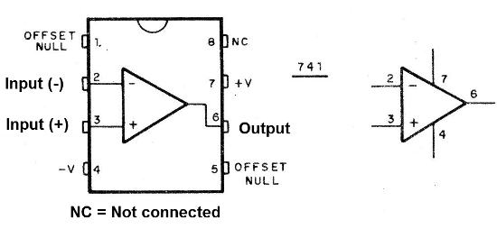
The 741 is not a power amplifier, like any operational amplifier of this type.
It is a component that has two inputs. When we apply a signal at the non-inverting input (+), the signal appears amplified at the output with the same phase. In other words, a positive variation of the input voltage appears as a positive variation of the output, or in simpler language: when the voltage "rises" in the input it also "rises" in the output.
When we apply a signal to the inverting input (-), the signal appears on the output with the inverted phase.
In other words, when the voltage "rises" in the input, it "goes down" in the output (Figure 2)

The input resistance of the ideal operational amplifier must be very high and the output resistance very low. In practice, the input resistance depends on its amplification, reaching 1 M, whereas in the output is on the order of 50 ohms.
By connecting the output of the operational amplifier to the inverting input directly or through a resistor, we can control the amplification. It can typically range from 1 to 100,000 times.
To use the 741 Operational Amplifier, we may need two types of source.
In one case, we have the so-called simple source, in which we use a single voltage of a battery, as shown in Figure 3.
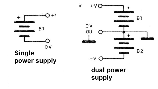
In another, we need a positive voltage and a negative ground. We say in this case, shown also in Figure 3, that the source is symmetric.
See then that, we use the operation with a symmetrical source, without the input signal, the output is 0 V (half of what the two batteries in series provide). If the signal applied at the non-inverting input is positive, the output tends towards the positive and if it is negative, it tends towards the negative.
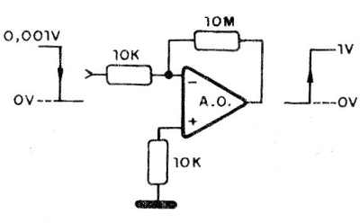
If the operating gain is 1 000 times, a voltage of 1 mV (0.001 V) at the input causes a "rise" or "descent" of the output voltage of 1 V. (Figure 4)
Seen this, we can assemble our integrated in the experience board and go to:
1. Amplifier with variable gain
For this experiment we need the following material:
Cl-1 - 741 - operational amplifier
R1 - 10k x 1/8 W- resistor (brown, black, orange)
R2 - 10k x 1 / 8W - resistor (brown, black, orange)
P1 - 1M - potentiometer
P2 - 47k - potentiometer
M1 - 0-6 V voltmeter or multimeter
B1, B2 - 6 V - 4 small alkaline batteries or symmetrical source
Miscellaneous: wires, contact array board type, etc.
The assembly on the contact array is shown in Figure 5.
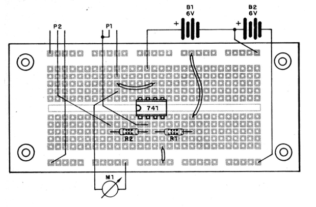
What we are going to do is check the gain of an operational amplifier as a function of the feedback.
By observing the circuit, we can see that the potentiometer P1 of 1M can control the feedback of the integrated one and thus determine its gain.
This gain depends on the relationship between the resistance given by the potentiometer and the input resistance (R1) of 10 k.
Thus, in the position where the potentiometer is at the minimum of resistance, we have the minimum gain equals to 1. In these conditions varying the input voltage between 0 and 6 V, we will have in the output an equal variation.
With the potentiometer in the maximum resistance (1 M) position, the gain will be 100 times. Thus, a small movement in the input potentiometer (47 k) will cause the voltage to reach the maximum. A voltage of 0.06 V will already lead to the output at 6 V. We will then have the so-called "saturation".
The curve of Figure 6 shows the behavior of the operational amplifier, with the saturation regions.
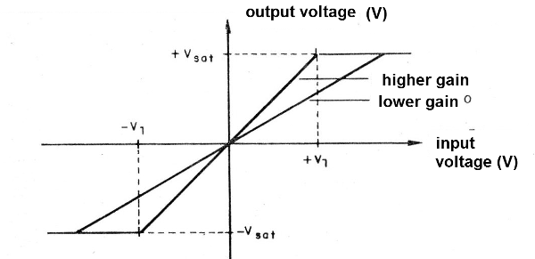
The slope of the line corresponding to the linear operating zone depends precisely on the gain adjusted by the feedback.
Moving the potentiometer P2, due to several adjustments of P1 and giving the instrument needle deflection in this experiment, you can see what happens.
2. Oscillator (astable)
Astable multivibrator with an operational can be done with ease, as we will see.
The material for this is as follows:
Cl-1 - 741 - operational amplifier
R1, R2, R3 - 10 k x 1/8 W- resistor (brown, black, orange)
C1, C2 - 10onF - ceramic capacitors
C3 - 47 nF - ceramic or polyester capacitor
B1 - 6 V or 4 small batteries
Miscellaneous: contact array, wires, etc.
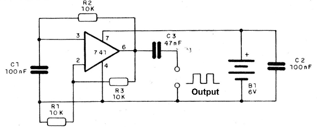
The principle of the operation of this circuit is simple: if we take part of the output signal and throw it back to the non-inverting input we will have a positive feedback, which leads the circuit to oscillation.
The frequency of oscillation depends on the time constant of R1 and C1.
For the values indicated in the diagram, we have a frequency of approximately 1 kHz. If we want to increase the frequency, we decrease C1.
We note, however, that as the frequency increases, the gain of the amplifier falls to the point where the oscillations can no longer be maintained.
The point at which this occurs for the 741 is around 1 MHz.
In Figure 7 we have the circuit for this experiment.
The complete assembly is shown in Figure 8.
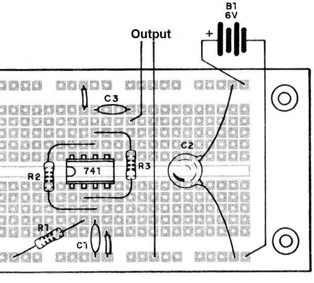
You can use this circuit as an efficient signal injector.
A headset connected to the output allows you to hear the generated audio signal.
Revised 2017


