

Obs. This article is art of one of my books published in USA.
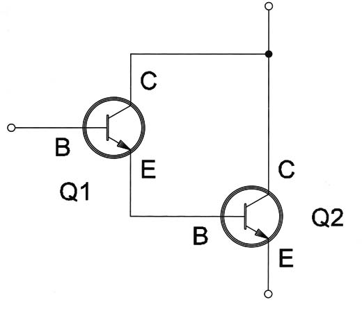
Figure 1 – Darlington transistors
For example, if two transistors with gains equal to 100 (B =100) are placed together to form a Darlington pair the final gain will be 100 x 100 or 10,000! They function as a single transistor with 10,000 of gain.
A Darlington transistor can be manufactured by placing two transistors in the same silicon chip, packing them inside a common enclosure forming a super transistor.
Darlington transistors are useful where high gain is necessary, such as in solenoid, motor, relay, or lamp drivers as well as high-power audio amplifiers.
Symbols
The symbols for Darlington transistors are shown in Figure 2.

As a common bipolar transistor, they are found in the NPN and PNP versions.
High-power Darlington transistor must be mounted on heat-sinks.
By the simple look of the component it isn’t possible to know if it is a common transistor or a Darlington transistor, or any other semiconductor because they all use the same bodies.
The identification is made by the type or part number that is normally a figure on the component’s body.
Specifications
If you have a handbook of transistors or the specific data sheet (or diagram) for the equipment, it is possible to know if the component is a Darlington transistor.
A common series of Darlington transistors found in many electronic appliances and even in electric applications is the TIP series of Darlington transistors first manufactured by Texas Instruments and now by many other manufacturers.
This series is formed by a number of Darlington NPN and PNP transistors designed to control currents from 1 A to more than 10 A and voltages up to 100 V and possibly even higher.
Some Darlington power NPN transistors in this series are TIP110, TIP111, and TIP112 for 2 A of collector currents. The complementary PNP types are the TIP115, TIP116, and TIP117.
Important: Not all transistors beginning with TIP are Darlington transistors!
The data sheets or data books normally have a lot of information about transistors including many curves and numerical information about performance.
For electricians or even electronic technicians who only want to know enough to use or replace a Darlington transistor the following specifications are the most important.
A. Collector-Emitter Voltage (Vce)-the maximum voltage that can be applied between collector and emitter of a transistor. Typical values range from some volts to more than 400 volts. In some data books a third letter or group of letters is found after the “ce” indicating special conditions for the value. We can find a (max) indicating that it is the maximum value or a (typ) indicating that it is a typical value.
B. Collector Current (lc)-the maximum current that can be controlled by the device. This current flows between collector and emitter when the transistor is in the conducting state and varies from some milliamperes to more than 20 amperes to even more heavy-duty types. The additional indication of (max) can also be found with the values.
C. Gain (hFE)-Gain for common Darlington transistors can vary from 1000 to more than 10,000. For what the gain means, refer to specifications in for bipolar transistors.
D. Dissipation Power (Pd)-The transistor generates heat when it conducts a current, which is transferred to the area surrounding the transistor. The Dissipation Power in watts gives the maximum amount of heat that can transfer to the surrounding area. Small-signal transistors can have dissipation in the range of milliwatts, but high-power types can dissipate powers up to 250 watts and more.
E. Transition Frequency (fT)-Darlington transistors are slow devices and can’t operate in frequencies above some hundred kilohertz. The maximum theoretic operation frequency is given by the transition frequency of fT (the gain falls to 1) and is typically near 100 kHz for most common types.
Where they are found Many common appliances use Darlington transistors to drive high current loads including solenoids, electromagnets, motors, and lamps. This is shown in the example circuit in Figure 3.

The load is connected between the power supply and the transistor’s collector. When the transistor is biased it conducts the current energizing the load.
In this configuration the transistor acts as a switch turning on and off the load according to the base current.
You can find transistors like these driving solenoids in electric appliances, electric doors, and in electronic equipment such as VCRs and DVD players.
Darlington transistors can also be used as low-frequency amplifiers in other applications (Figure 4).

The audio signal (corresponding to a sound) is applied to the transistor’s base where it is amplified.
Then the transistor triggers a loudspeaker where the signal is reproduced.
Two complementary Darlington transistors (Figure 5) are found in many hi-fi audio amplifiers.

This kind of circuit can drive a loudspeaker with powers up to 250 watts.
Testing
Darlington transistors can be tested the same way as common bipolar transistors. Using a multimeter, you can measure the resistances between electrodes (base, emitter, and collector) according to the type (NPN and PNP).
Refer to the item about bipolar transistors and how to test them. Remember that some multimeters have the transistor test function that can be used with Darlington transistors.


