
Note: This is yet another article in a series on digital electronics in this site.
Thus, manufacturers soon developed families of components (integrated circuits) that brought together a number of interconnected elements with which they had the most diverse logical functions, flip-flops, and many other circuits of utility in digital electronics.
A family of digital integrated circuits consists of a series of types, corresponding to functions, flip-flops and other devices which we will study with compatible characteristics so that they can be fed by a common source and directly interconnected without the need of many external elements and in some cases, none.
By bringing together these components from the same family, you can design the most diverse digital circuits, such as counters, timers, calculators, computers, control and automation machines, etc.
Currently we have two basic families that are widely used in the projects, given their low cost and the ease with which we can get in the specialized trade the many existed functions.
From these families derive some subfamilies which are used in computing or in the elaboration of special projects in which demand low consumption, high speed or other characteristics that the normal families cannot provide.
In Figure 1 we have an example of an integrated circuit of a digital logic family quite common in DIL enclosure (most common).
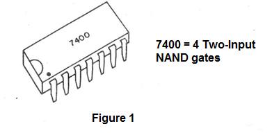
This component brings together 4 NAND logic gates which can be used independently and can be perfectly interconnected in an application where this is necessary.
Integrated with hundreds, even thousands of ports, or other functions, are now available for more complex projects.
The TTL family
The name TTL comes from Transistor-Transistor-Logic, this family being the most popular for its low cost, good speed and low consumption.
The built-in TTL family must be supplied with a voltage of 5 V. A tolerance is allowed which leads it to normal operation with voltages between 4.5 and 5.5 Volts.
The transistors used in the TTL integrated are the multi-emitter type, as shown in Figure 2.
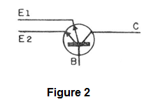
Each emitter acts as a diode, thus providing insulation to the input relative to the circuit which drives it. Thus, two circuits, one at each TTL input, will not have any kind of interaction.
There are several TTL subfamilies, which are variations with different characteristics regarding speed and consumption.
So we have the High-Speed ??TTL which operates at higher speeds, but also requires more power for operation. On the other hand, the Low-Speed ??TTL (slow speed) operates more slowly, but has extremely low power consumption.
In computing we have the Low-Power Schottky which is characterized by high speed and low power consumption, being fully compatible with the internal circuits of most microprocessors and microcontrollers. This subfamily is used in interfaces and shield projects.
In Figure 3 we have a typical NAND TTL port through which we can analyze its operation. The others are quite similar.
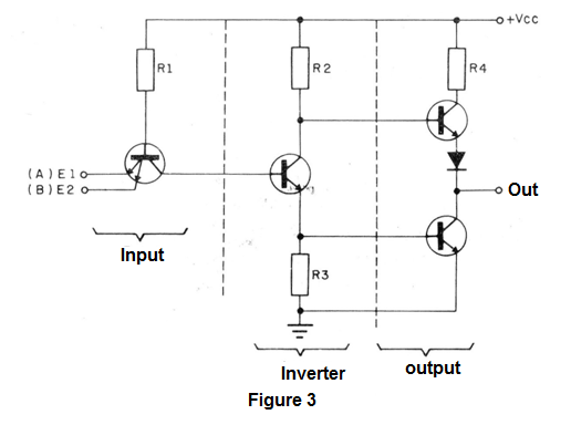
We observe the multi-emitter transistor in the input, which in this case has two, because there are two inputs.
This stage feeds a phase inverter with one more transistor, which in turn drives a higher power output stage with two transistors in series.
The electrical input and output characteristics of TTL circuits are the ones that are most important in the design of any project.
So let's set some important terms regarding them.
LO Level
What voltages does the integrated TTL interpret as a 0 or LO? This knowledge is useful in any project.
Voltages between 0 and 0.8 V are surely interpreted as LO. The value 0.8 V is represented by VEL.
HI Level
The lowest voltage that can be interpreted as HI is 2.4 V. Thus, values ??between 2.4 and 5 V are sensed as Hl or 1 by TTL.
We can draw a graph where we have two distinct ranges of operation for the TTL integrated (see Figure 4).
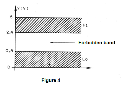
Tensions outside this range are prohibited for TTL integrators, as we cannot guarantee that they are interpreted by 0 or 1.
What we have seen is the transfer characteristic of an ITL.
At the output of each integrated we can guarantee that the signal levels in LO and HI will also be in this range, which also guarantees the possibility of the interconnection of several integrated ones.
It is time to define what is loadable or fan-out.
If at the output of an integrated TTL we have a voltage level HI, say around 4 V, the moment we connect more than one TTL input of other ports, they "load" the circuit in order to reduce the voltage (see Figure 5).
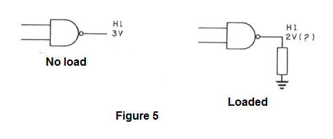
The result is that this voltage can fall below the range limit where the integrated interprets the voltage as "1" thus inducing the system to erratic operation.
There is, therefore, a limit to the amount of inputs which we can connect to the output of a TTL and this is called a fan-out.
A standard (standard) built-in TTL can drive 10 normal TTL inputs.
Here's an important table that shows the "fan-out" capabilities of the various cross-TTL subfamilies.
Normal TTL:
can drive 10 normal TTL inputs
can drive 40 low-power TTL inputs
can drive 6 high-power TTL inputs
can drive 20 low-power Schottky inputs
can drive 6 TTL Schottky inputs
Low-power TTL:
can drive 2 normal TTL inputs
can drive 10 low-power TTL inputs
can drive 1 high-power TTL input
can drive 1 TTL Schottky input
can drive 5 low-power Schottky TTL inputs
High-power TTL:
can drive 12 normal TTL inputs
can drive 40 low-power TTL inputs
can drive 10 high-power TTL inputs
can drive 10 TTL Schottky inputs
can drive 40 low-power Schottky TTL inputs
Schottky TTL:
can drive 12 normal TTL inputs
can drive 40 low-power TTL inputs
can drive 10 high-power TTL inputs
can drive 10 TTL Schottky inputs
can drive 40 low-power Schottky TTL inputs
Schottky Low-power ITL:
can drive 5 normal TTL inputs
can drive 20 TTL low power inputs
can drive 4 TTL high power inputs
can drive. 4 TTL Schottky inputs
can drive 10 TTL low power Schottky inputs
It is also important to know, in the normal TTL family, which are the currents that we have in the inputs to drive and the one we have in the outputs:
Thus, a normal TTL provides at its output a maximum current of 16 mA, while its input needs a current of at least 1.6 mA to be driven.
The normal TTL series start with the type 7400. All others begin with the number "74". There is also a military variation of this series which is the 5400.
Subfamilies have additional letters in the types that indicate which ones they belong to. So we have:
High-power - 74H00
Low-power - 74L00
Schottky - 74S00
Low-power Schottky - 74LS00


