Changing the coded signal, the angular position of the shaft also changes.
Figure 1 shows a typical servo for applications in Remote Control (RC).
The most popular use of the servo is in radio controlled airplanes to position control surfaces like the elevators and rudders. But, of course they are a good option to other applications as the ones related with mechatronics: car, robots, arms, etc.
High power units can also be used in other applications as industrial automation.
Operation principle
Servomotors are closed loop devices. Given a signal it adjusts itself until it matches the signal. If the signal changes, the motor changes to match them.
The servo motors are geared DC motors with a positional control closed loop that allow them to be used as position control.
a) Basic Principle
The basic configuration of a servomotor is shown by figure 2.
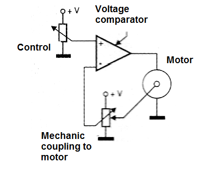
A DC motor is used to move a gearbox with a large reduction ratio.
The final shaft, moving at a very low speed, releases a force to the external load and at the same time acts on the axis of a feedback potentiometer. This potentiometer senses the position of the axis sending to an operational amplifier (plugged as a voltage comparator) a correspondent voltage.
This voltage is compared with the input voltage (that determines the position we want to the shaft) producing a voltagein the ouput of the comparator. This voltage will power the motor such a way they will move the shaft in the necessary direction to find the angle correspondent to the voltage applied to the input.
-->b) Standard
Another way to control the position of the shaft of a servo is using a coded signal. This operation is found in standard servos used with RC applications as cars, airplanes, toys, etc.
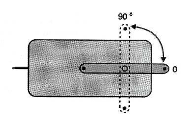
As shown by figure 3 the signal applied to the control input of the servo is a train of pulses with a total period 18 ms.
The duration of the pulse will determine the position of the shaft in a range of 180 degrees as shown by the same figure.
If the pulse is 1,5 ms long, the servo motor will be positioned in the midrange. If the pulse is 1 ms long the servo will be 90 degrees left and if the pulse is 2 ms long (corresponding to a frequency of approximatelly 50 Hz) the servo will be 90 degrees right.
Other types can have a range of pulse lengths between 1.25 ms and 1.75 ms.
In this case, the shaft will be at the center with 1.50 ms, 90 degrees to the left with 1.25 ms and 90 degrees to the right with 1.75 ms.
Types
The standard servo has three wires: two for power (between 4 and 6 volts) and ground and the last for control.
The colors for the wires are:
Red - +Vdc
Black - Ground
White - Control
The size and shape of a servomotor depends on the application.
Figure 4 shows some common type of servo motors used in RC and mechatronics. They are low power servos that can be powered from cells, small batteries and other DC supplies in the range from 100 mA to 2 A .
There are also high power types powered from AC supplies used in industrial and motion applications (Figure 5).
(Figure 5)
Characteristics
As other types of motors the servomotors have electrical and mechanical characteristics. The main are:
Power supply voltage
The types used in RC normally can be powered from supplies in the range from 4 to 6 V. Special types can be found with voltages out of this range.
Current
Is the current drained by the motor when the maximum torque is applied to na external load. As in DC motors, this current changes according the load. Common servos have maximum currents in the range of 100 mA to 2 A.
Operating Speed
Is the time delay necessary to the shaft reach a specified position (normally 60 degrees). Common servos have operating speeds in the range of 0.05 to 0.2 s/60o
Torque
As in other types of motors the torque is given in kg/cm or N/cm. Typical values are in the range from 0.5 to 10 kg/cm. See Part 4 and 6 for informations about how to measure the torque of a motor or a solenoid. The procedures can be applied to servo motors.
Control Pulses
Is the type of pulse used to positioning the shaft. Two main types are used in RC applications: central position in 1-2 ms and 1,25-1.75 ms.
In the 1-2 ms type, the pulse width ranges from 1.25 and1,75 and in the 1.25-1.75 ms type the range is between 1 and 2 ms.
Resolution
Is the precision the shaft is positioned when receiving an external command signal. Typical servos have resolutions in the range from 1o to 10o.
Size/Weight
This information is important do the mechanical part of a project. Small RC sevos have a typical range of weight between 15 and 200 g.
Table
Pulse Duration x Position Angle (for 1-2 ms servos)
| Duration (ms) | Angle (degrees) |
| 1 | -90 |
| 1.1 | -72 |
| 1.2 | -54 |
| 1.25 | -45 |
| 1.3 | -36 |
| 1.4 | -18 |
| 1.5 | 0 |
| 1.6 | 18 |
| 1.7 | 36 |
| 1.75 | 45 |
| 1.8 | 54 |
| 1.9 | 72 |
| 2 | 90 |
Table
Pulse Duration x Position Angle (1.25-1.75 ms servos)
| Duration (ms) | Angle (degrees) |
| 1.25 | -90 |
| 1.30 | -72 |
| 1.35 | -54 |
| 1.40 | -36 |
| 1.45 | -18 |
| 1.50 | 0 |
| 1.55 | 18 |
| 1.60 | 36 |
| 1.65 | 54 |
| 1.70 | 72 |
| 1.75 | 90 |
Formulas:
Pulse duration x position
t = { [ (α - 90) x (t2 - t1) ] / 180 } + t1
Position x Pulse duration
α = { [ ( t – t1 ) x 180 ] / (t2 - t1) } + 90
Where:
t is the pulse duration for a determinated position (ms)
α is the angle of position of the shaft (degrees)
t2 is the upper limit of the pulse length (ms) - 1.75 or 2
t1 is the lower limit of the pulse length (ms) - 1 or 1.25
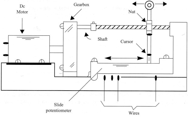
Building a Simple Servo
The reader can build his own experimental servo using common parts. Figure 6 gives a simple project.
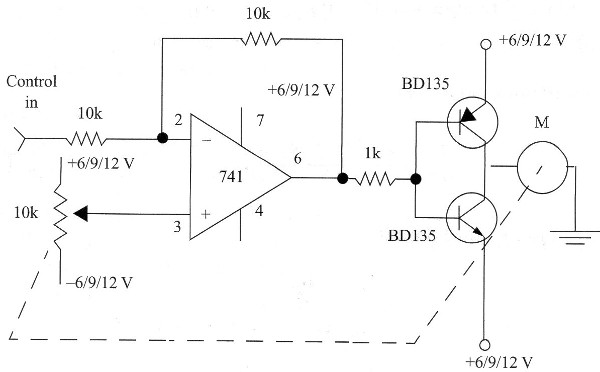
This servo is controled by a voltage instead pulses (we can adapt it to operate with pulses).
The circuit is shown by figure 7.
A gearbox is adapted to a worm screw that moves a nut. The nut is coupled to a slide potentiometer that gives the electric feedback to the circuit.
When you apply a voltage to the input of the circuit (signal) the motor moves until the potentiometer reaches the position where the feedback voltage is equal to the input voltage (zero output). If you change the voltage in the input, the motor will be powered until the potentiometer reaches a new position where the output is zeroed.
Advantages of Servo Systems over Stepper Systems
Servo and stepper motion control systems have a basic difference: the use of feedback . Servos have a position encoder attached to the drive motor that reports the actual position of the motor shaft back to the controller. If there are any errors present, the servo controller may take corrective action to insure the motor reaches the proper position.
In the other hand stepper controllers can only issue a move command and hope that the motor is capable of following it. You have no way of determining for sure that they had reached the desired position. The presence of feedback in a servo controller system results in several benefits:
No Lost Pulses
Servo systems know exactly where the motor is at all times, so all step commands are executed.
Full Torque at High Speeds
Stepper motor torque falls off as motor speed increases due to electrical time constants and poor current utilization. Servo motors do not have this problem and may generate full torque at high RPMs.
Quiet - Smooth Operation
Servo systems are inherently smooth due to their high encoder resolutions, typically at least ten times finer than the number of stepper motor positions per revolution.
Zero Holding Current
Stepper motors must have high currents applied at all times, even while stopped with little or no load. Servo systems drain power only as required - proportional to the load torque applied to the motor.
True Microstepping
Stepper motors may increase their resolution by a process called microstepping where currents are applied to the motor windings proportional to the desired position between normal steps.