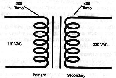
When an alternating voltage is applied to one coil of a transformer (called the primary winding), this voltage induces alternating voltages in the other coils (secondary windings) depending on the ratio of turns of the two windings.
For example, if a transformer has a primary winding with 200 turns and a secondary with 400 turns, and 110 VAC is applied to the primary, 220 VAC can be found in the secondary, as shown in Figure 1.

Transformers can be used to change voItages, currents, and impedances in an aIternating-current circuit or high-frequency circuit.
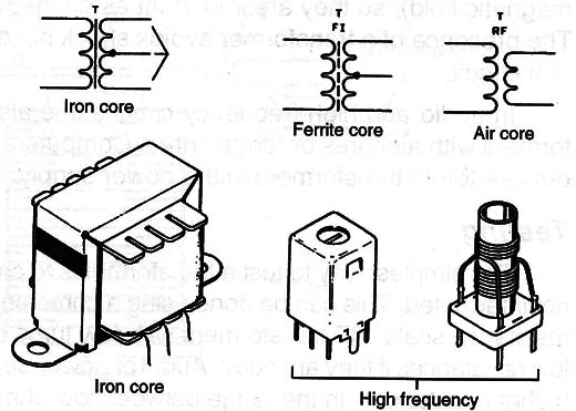
The transformers can be wound in forms with air cores, ferrite cores, or iron cores according to the application.
Air and ferrite cores are used in high and medium-frequency circuits and iron cores are used in medium and Iow-frequency circuits.
Symbols and Types
Figure 2 shows the different symbols used to represent transformers and their types.

The presence of a material core (ferrite or iron) is represented by a continuous or intermittent Iine.
If the Iine is absent it is an air core transformer.
Specifications:
Audio and power supply transformers
- Input voltage or impedance-The primary winding or the input of a transformer is specified by the voltage such as the transformers found in power supplies. In transformers used as an impedance match in audio or other applications, the primary winding is specified by an impedance in Ω.
The output voltage-The secondary winding of a power supply transformer is specified by the output voltage and current. For audio transformers the output impedance, and in some cases, also the output power, are given.
RF Transformers
- Number of turns-In RF transformers the number of turns and the wire gauge are specified, mostly in circuits to be mounted.
- Core-The type of core and format is an important specification for high-frequency transformers.
Where they are found
The reader wiII find transformers of many sizes and types in all electronic equipment. The most common types are the transformers used in the power supply of any equipment.
The windings are isolated one from the other (the electric energy is transferred from one to the other by the magnetic field), so they are important as an insulation element in circuits.
The presence of a transformer avoids shock hazards when touching parts of a circuit.
In audio and high-frequency circuits it is also possible to find transformers with air cores or ferrite cores.
Computers and some audio amplifiers use toroid transformers in the power suppIy.
Testing
The simplest way to test a transformer is to check that the windings are not interrupted.
This can be done using a common muItimeter on the Iowest resistance scaIe. RF transformers with few turns of wire must present very Iow resistances if they are good.
Audio or power-supply transformers present higher resistances, in the range between Iow Ω and 10,000 Ω.
The measured resistance of the winding of any transformer isn’t ots impedance but the ohmic resistance of the wire used to wind it.


