Thyristors are four-layer semiconductor devices basically intended for applications of control and AC circuits. They are solid-state switches, can operate at voltages up to many hundreds of volts, and can handle currents up to hundreds of amperes.
As the SCR is very important to the reader who wants to know how electronics devices are used in electric installations, more space than the usual dedicated to other components is given to their description and applications. So, what is an SCR, starting from its structure?
Figure 1 shows the structure of an SCR and the equivalent circuit formed by two complementary transistors. It is a silicon semiconductor with a PNPN structure.
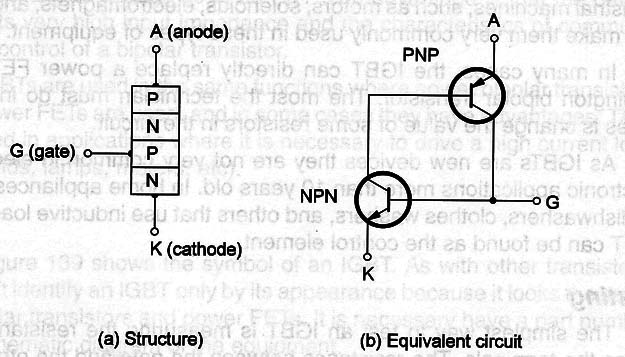
In the basic operation the anode (A) is made positive and the cathode (K or C) negative. The load is placed between anode and the power supply.
If no voltage is applied to the gate (G) the two transistors remain off and no current can row across the load. But, if enough voltage is applied to the gate, it can make the NPN transistor conductive and a current begins to row between its collector and emitter.
This current is the one that comes from the base of the PNP transistor biasing on this component. The current that now begins to row by the NPN transistor acts as a feedback to the NPN transistor as it also rows through its base.
The feedback makes all the currents in the circuit increase speed and in a few microseconds the circuit reaches a saturated state. The current between the collector of the PNP transistor and the emitter of the NPN transistor is now at its maximum value.
After completion of this very fast process, even if the initial voltage that started all this is no longer present, the device remains conductive.
In a real SCR the process is the same: a positive voltage applied in the gate triggers on the device that conducts the current from the anode to the cathode
Even if the voltage disappears once it is triggered, the device is kept in the on state. To trigger it off there are two possibilities:
1. Turn off the power supply for a moment. This makes the device current fall to zero.
2. Reducing the current rowing through the device to a value that cuts the feedback process. A short between anode and cathode, reducing the voltage to zero (Figure 2), can be created to trigger the SCR off.
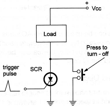
Notice that the SCR acts as a diode that can be made conductive or not conductive because the current flow only can flow in one direction.
This explains its symbol-a diode with a gate. Real SCRs can be triggered by voltages of about 1 volt and currents ranging from 100 microamperes for the most sensitive to some miliamperes for high current types and less sensitive types.
If placed in an AC circuit like the one shown in Figure 3, when turned on the SCR can conduct only the positive semi-cycles of the AC power line voltage.
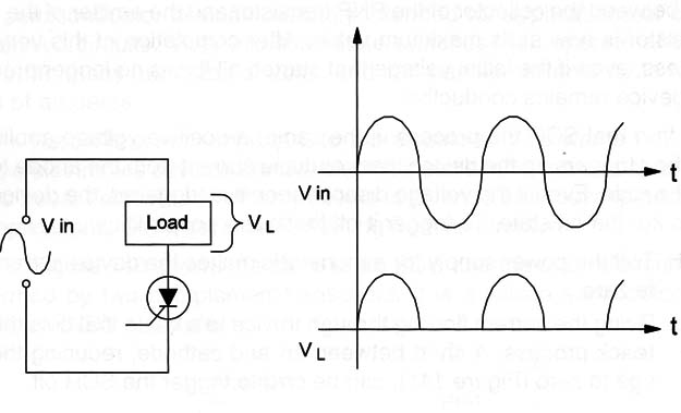
The SCRs can be used to control AC loads directly from the AC power line. The most common types can operate handling high voltages and high currents.
This is because this device can be found in many applications related to the AC power line.
Symbol and Diagram
Figure 4 shows the symbol adopted to represent an SCR. the main types found in electronic equipment are shown in the same figure.
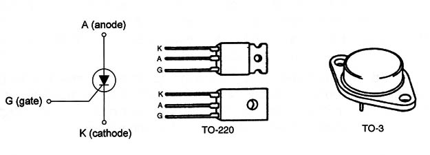
Although small SCRs designed to control low currents still exist, more of them are power devices including resources to place them on large heat sinks. The tab or the metal body of the SCRs used to be connected to the anode terminal.
Specifications
The SCRs are identified by a part number given by the manufacturer on the body. From this part number, looking in a handbook, in a databook, or on a data sheet it is possible to know the electrical characteristics.
When using any SCR it is important to know the following characteristics:
A. Maximum voltage between anode and cathode-the maximum voltage that can be applied to the SCR when it is in the off state. Typical values range from 50 to more than 1000 volts for common types. This specification can also be indicated as Repetitive Peak Off voltage and abbreviated by Vdrm or as Repetitive Peak Reverse Voltage and abbreviated by Vrrm.
B. Maximum current-the maximum current that the SCR can hold when in the conductive state. Common SCRs found in AC-powered appliances are specified to control currents in the range from a fraction of an ampere to more than 50 amperes.
C. Dissipation power-When an SCR is on, independently of the current it is conducting, the voltage between anode and cathode is about 2 volts. The product of this voltage by the current gives the dissipation of the SCR. The maximum dissipation of an SCR is important to know in order to calculate the size and shape of the heat sink.
D. Holding current-the lowest current that the SCR can conduct without turning off. This current is abbreviated by lH.
Other important specifications are the speed of the device given by the value referred to as Critical Rate of Rise of Off State Voltage and measured in volts by microseconds.
This value shows how fast the voltage applied to the load increases when the SCR is turned on.
Where they are found
SCRs are found in several applications involving AC power control. Some devices where SCRs can be found are motor controls, timers, dimmers, alarms, solenoid drivers, and many home appliances.
The most common application of an SCR as a power control is the one shown in Figure 5.
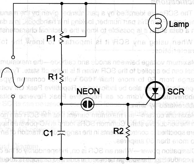
This circuit is found in commercial dimmers like those installed to replace common on/off switches. It is also used to control the brightness of incandescent lamps, in fans as a speed control, and in heaters as a temperature control.
It is very important for the reader to know how this circuit works because its operation principle is applied to a large number of common electric appliances that have a power (speed, temperature, etc) control.
Look at the waveform of the AC power line voltage shown in Figure 6.
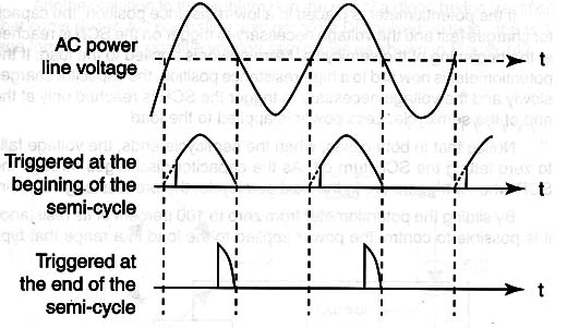
The voltage changes make the current flow forward and backward across a load determining the amount of power absorbed by it. This can be reduced if we cut the semi-cycles of the AC power line voltage in different points.
For example, if the semicycles are cut at the end, only a small part of the AC power line voltage passes and is applied to the load. If it is a lamp it will present a low brightness.
If it is a motor it runs at low speed. If it is a heater the temperature is lower. If the semi-cycle is now out at the beginning, a larger part of the power passes and is applied to the load. it it is a lamp, the brightness is increased, a motor runs at a higher speed, and a heater is warmer.
Using an appropriate control, we can slide the point where the semicycles are cut from near zero to 100 percent and thus control, with a great precision, the amount of power applied to a load.
The circuit shown in Figure 5 makes this control. At the beginning of a semi-cycle of the AC power line the voltage applied to the capacitor C increases in speed depending on the value of the component and the value of the resistance adjusted in the potentiometer P1.
If the potentiometer is placed in a low-resistance position, the capacitor charges fast and the voltage necessary to trigger on the SCR is reached at the beginning of the semi-cycle. More power is applied to the load.
If the potentiometer is now slid to a high-resistance position, the capacitor charges slowly and the voltage necessary to trigger the SCR is reached only at the end of the semi-cycle. Less power is applied to the load.
Notice that in both cases, when the semi-cycle ends, the voltage falls to zero letting the SCR turn off. As the capacitor discharges through the SCR when it triggers on, in the next semi-cycle, the process begins again.
By sliding the potentiometer from zero to 100 percent of its resistance it is possible to control the power applied to the load in a range that typically goes from near 0 to 95 percent of the maximum power.
A little prob- lem must be considered in this circuit: the SCR is a unilateral device and the AC loads must receive both semi-cycles to reach their normal maximum power. How can this problem be solved?
In some cases the circuit can operate only with the positive semicycles of the AC power supply line, and the SCR can be used. in other cases, two SCRs wired in an anti-parallel mode are used, as shown in Figure 7.
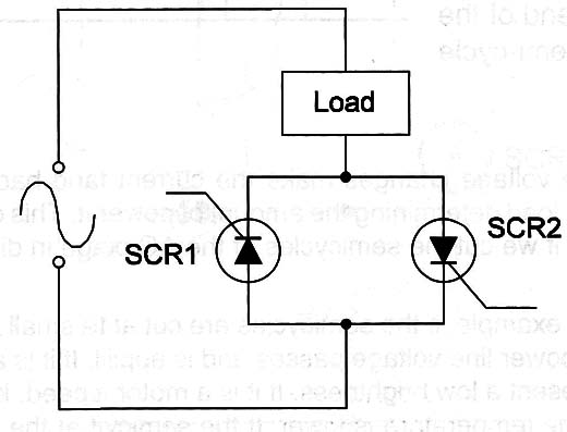
One SCR conducts the positive semi-cycles and the other conducts the negative semi-cycles of the AC power line voltage.
Another solution to the problem is in the use of a diode bridge (rectifier) that converts the AC power line voltage into a DC pulsed voltage, or a voltage formed only by positive voltage semi-cycles as shown in Figure 8.
Figure 8 – Using a diode bridge
But, the best solution is in the use of another device of the thyristor family-the triac. The triac can be considered as two SCRs inside a unique case that can be used to control both semi-cycles of the AC power line voltage.
The SCR is not used only as a power control. Many other configurations are possible including timers, oscillators, alarms, automatic switches, and protection circuits (crowbar).
The 106 Series
One of the most popular series of SCRs found in many electronic circuits is the 106 series. It is formed by low-cost general-purpose SCRs that can control currents up to 3 or 4 amperes (3.2 volts average for the TIC106) in circuits having voltages in the range between 50 and 1000 volts.
The devices of this series are very sensitive; they can be triggered from currents as low as 60 µA (typical). The part number of the SCRs of this series begins with a group of letters identifying the manufacturer followed by 106, and a figure indicating the maximum operating voltage.
Some examples follow.
MCR106-B (Motorola - the B indicates it is for 200 V)
TIC106-6 (Texas Instruments for 400 V)
IR106 (International Rectifier)
C106 (General Electric)
Testing
SCRs can be tested with a multimeter. In normal conditions the device is an open circuit when the resistance between anode and cathode is measured (the multimeter will indicate infinite).
If a low resistance is measured in this condition the SCR is shorted. The other test consists of the verification of the gate-cathode junction that acts as a diode. In one direction a low resistance is found and in the opposite direction a high resistance is found if the device is in good condition.


