A capacitor is a component formed by two conductive elements called “armatures”, which are separated by an insulating substance called “dielectric”. It is usually the dielectric which names the capacitor.
So if the dielectric of a capacitor is ceramic, we have a ceramic capacitor; if it is polyester (a kind of plastic), the capacitor will be polyester, and if it is paper, capacitor will be paper. In Figure 1, we have the basic structure of a capacitor and the symbol used for its representation.

The purpose of the capacitor is to “store electricity”. When we connect a capacitor to any source of electrical power, positive charges flow to one armature, and negative charges to the other, just as much "attached" to the component as shown in Figure 2.

Discharging the capacitor simply touch the wire of one armature to the wire of the other. The charges flow so that the positive cancel the negative. The capacitors are specified by two values: capacitance and working voltage.
The capacitance tells how much charge “fits” in the capacitor under certain conditions. The unit is Farad, abbreviated by F, but as it is a very large unit, it is preferable to use submultiples such as:
Microfarad, abbreviated by uF worth 0.000 001 Farad or the millionth part of Farad.
Nanofarad, abbreviated by nF worth 0.000 000 001 Farad or the billionth part of Farad.
Picofarad (also called micromicrofarad) abbreviated by pF (or ppF) worth 0.000 000 000 001 Farad or the trillionth part of 1 Farad.
We then see that 1 microfarad is worth 1,000 nanofarads or 1,000,000 picofarads and that 1 nanofarad is worth 1,000 picofarads.
Some capacitors are marked, instead of “uF”, with “mfd”, especially the older ones. The working voltage tells you how much the capacitor can handle when in use. We cannot "charge" a 600 V capacitor over 600 V as this can "pierce" its dielectric, meaning it loses its insulating properties and stops working.
We must respect this indication, always applying to the capacitor a voltage lower than the maximum indicated.
CODES
There are many types of capacitors, and depending on manufacturers, value marking can take different forms. Readers who have “hills” of scrapped or even purchased capacitors sometimes find it difficult to use them and often use wrong types for certain functions, which leads to malfunctions.
It is common to use 47 nF, or even 4n7 capacitors, instead of 4.7 pF in FM transmitters, which causes them to be inoperable. Let's look at the codes:
a) Small Ceramic Capacitors
We call “small” the capacitors of the order of picofarads, usually of the ceramic type with the disc or tubular shape, as shown in Figure 3.
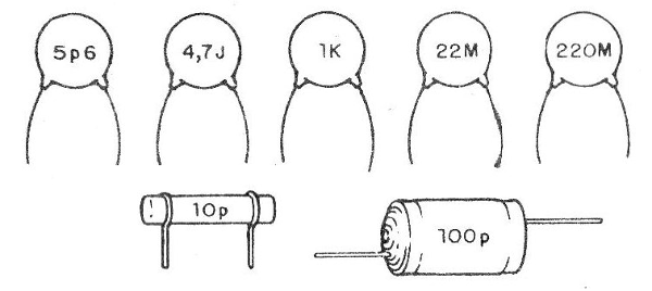
In this figure we have the many ways to do the value marking. The letter “p” (lower case) indicates that the unit is the picofarad and can come either at the end of the value or in place of the comma. Thus, 4p7 means 4.7 pF (picofarads). Similarly 1op indicates 10 picofarads.
In these types, it is common to follow an uppercase letter after the value indicating the tolerance, which in our case is not important, except when specified in a project this letter can be J, K, M etc. In particular we draw attention to the upper case “K”, which can be confused with the lower case “k”, which indicates that the value must be multiplied by 1 000!
So 10K is 10 pF while 1ok means 10,000 pF or 10 nF!
Attention!
The values with which we find the capacitors usually follow the same series of resistors, i.e., in "jumps". So the most commonly used sequence is: 1 - 1.2 -1.5 - 1.8 - 2.2 - 2.7 – 3.3 – 3.9 - 4.7 - 5.6 - 6.8 - 8.2.
This means that we do not find a 1.3 pF capacitor because it is not in the series or 13 pF because it is not a multiple of this series in the same way as 190 pF. There are other older series that are used in some types like 1-2-3-5.
Thus we can have 500 pF, or 0.05 pF or 0.2 pF.
b) 3-number code
This is a code which appears mainly in ceramic capacitors and that makes the identification of the component very difficult for the less experienced.
As shown in Figure 4, 3 numbers (digits) are always used.
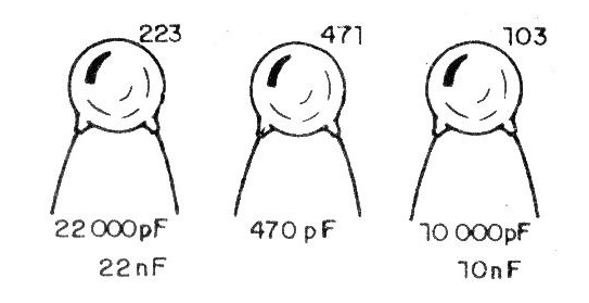
The first two give the two digits of the value and the third means the number of zeros to be added. The final value is then obtained in picofarads. To get in nanofarads we divide by 1 000. For example: 223 means 22 followed by 3 zeros or 22,000 pF which in nanoparads means 22 nF.
472 means 47 followed by 2 zeros or 4 700 pF which in nanoparads is 4.7 nF or 4n7 (n replacing the comma).
c) Decimal point code
In the American nomenclature instead of the comma a dot is used to separate units from unit fractions as in other countries. It is the decimal point. So, instead of writing 0,01; in the American system we have 0.01.
In capacitors, it is common to omit 0 before the comma, which means that instead of writing 0.01 uF only .01 uF is found. To get the value in nanofarads, in this case just multiply by 1000. So .01 uF is the same as 10 nF
d) Types and equivalences
Ceramic capacitors are flat or tubular capacitors and are suitable for applications in low frequency and high frequency circuits mainly. (Figure 5)
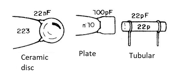
In projects that require this type of capacitor, it is not convenient to replace with another type. The value can sometimes vary slightly.
For example, if you don't have a 2.2 pF for an application, you might try 2.7 pF that the device will normally work. The polyester, paper and polycarbonate capacitors, shown in Figure 6, are best suited for low frequency circuitry, i.e., audio applications.
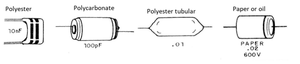
They can be replaced among each other, which means that if you don't have one type you can use another. In the absence of a "tablet" type polyester, you can use paper or oil from a discarded appliance.
The values themselves admit small variations. For example, if we ask for 22 nF, which is 0.022 or .022 uF, nothing prevents you from using an old .02 or even .03 uF (mfd) capacitor, as long as it looks good!
TESTING THE CAPACITORS
The following test shows only if the capacitor is shorted, i.e., if the dielectric has not been “pierced” by overloads losing its properties (Figure 7).
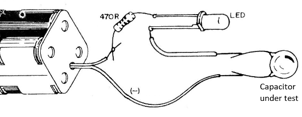
If the LED lights up, the capacitor is not good. If it remains off, it may be fine.
A better test for capacitors between 10 nF (.01 uF) and 500 nF (.05) is shown in Figure 8.
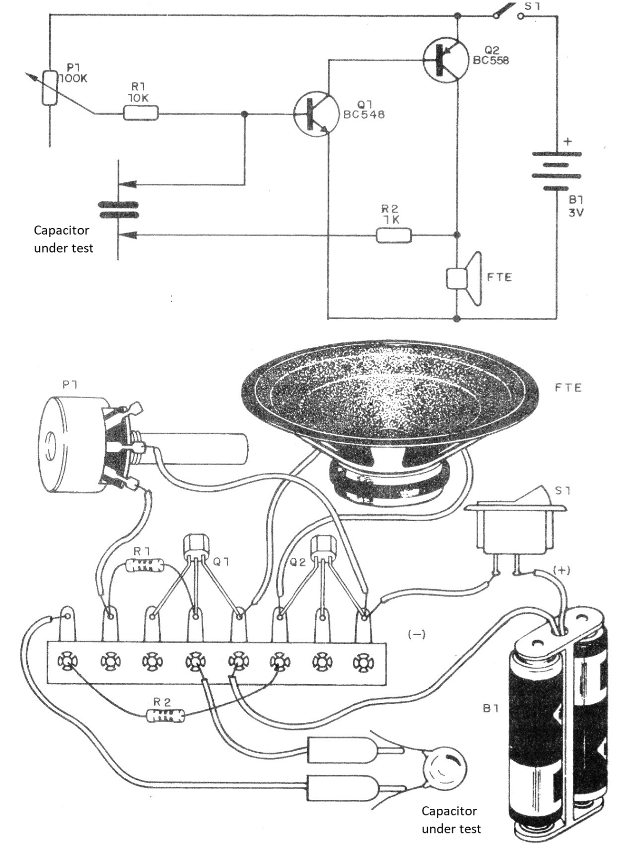
If the capacitor is good, the oscillator kicks in with a whistle which is set on the potentiometer. The higher the value of the capacitor, the lower is the frequency of the sound. If you have too many suspicious capacitors in your scrap, it will be good to have these proven.
Note that the paper and oil capacitors of old devices tend to "age" bearing in mind the moisture they absorb, and no longer have the properties which allow their use.