Alessandro F. Cunha
Note: This article is from 2007. The components given as examples are from the time. For a more up to date study or application, please look for available equivalents.
Potentiometers are resistors with a central shunt. Thus, the resistance between its two extreme terminals is fixed at its nominal value (10 kohms, for example). The resistance value between one of the ends and the central derivation will depend on the positioning of the cursor. A structure is then created that can be understood as two resistors in series, as shown in Figure 1.
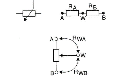
They are generally used in two ways: As a rheostat or as a potentiometer.
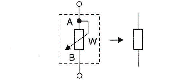
• Rheostat: The central terminal is connected to one end of the device. Thus, it acts as a variable resistor, as illustrated in Figure 2.
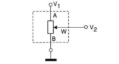
• Potentiometer: In this configuration, the three terminals are free and can be used as a voltage divider, providing an output voltage proportional to the input voltage and the position of the cursor, see Figure 3.
Analog Potentiometers
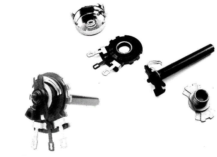
A mechanical potentiometer consists of a track of resistive material (carbon film, nickel wire, ceramic with metal - cermet -, etc.) through which an axis slides a terminal. The terminal contact with the track varies the resistance between the end terminals and the central terminal, as shown in Figure 4. The resistance variation is proportional to the displacement of the potentiometer's axis.
The operating accuracy of the mechanical potentiometer is directly linked to the type of material used in the construction of the track and the mechanical characteristics of the contact between the central axis and the track. Some even use multiple tracks to improve the contact area and decrease the chances of failure. Of course, this raizes the production cost.
Suppose the encapsulation where the contact between the track and the axle is has openings (as is the case with most potentiometers). In that instance, dust particles start to accumulate on the track, which causes the resistance of the contact between the axle and the track to increase. It affects the final resistance value, reduces the quality of the device, and generates unwanted noise in the signal coming out of the terminals.
Digital Potentiometers
A digital potentiometer is composed of an array of resistors in series, selectable by a logic control. Thus, the resistance between all elements in series will be the nominal value of the potentiometer.
The axis purpose, which will select a resistance position between the start and the end of the series, is carried out by a binary logic control, with defined discrete steps. The main difference between analogue and digital potentiometers: With the analogue ones, it is possible to obtain infinite resistance values between the shaft and one of the ends, and with the digital ones, only a fixed and pre-defined number of values ??can be obtained (usually 256).
Another difference is that, with the analogue ones, the adjustment of the cursor position is handled manually by the user. With the digital ones, a binary value must be entered in the component, and the value will cause the cursor to move internally through the switching of digital keys. The communication between the digital device and the user is usually carried through control circuits, often micro-controlled.
These devices use two basic triggers: Up and down counter circuits and binary word recording via a serial interface. The first mode is the oldest, most straightforward and easiest to use, as it is sufficient to take the voltage level on a microchip pin to logic level 1, and the steps will be increased. Bringing this same pin to logic level zero will decrement the steps.
The second mode requires the value of the step you want to adjust to being recorded in an internal register to implement this value in the potentiometer.
You can see that the first mode can only increment sequential values. On the other hand, the activation mode allows you to change from any step to any step, at any time, simply by entering the desired value.
Main Differences Between Analogue and Digital Potentiometers
• MTBF (Mean Time Between Failure): As mechanical movements cause wear on the moving parts of analogue potentiometers, the lifetime of the component, before failing, is much shorter than the digital devices.
• Nominal Resistance: Typical nominal resistance values available for digital devices are 1 kohms, 10 kohms, 50 kohms and 100 kohms. Resistance values less than 1 kohms is difficult to achieve on silicon microchips. Values greater than 100 kohms are easy to achieve but require a large material area, making the devices more expensive. Analogue devices have different values between 10 ohms and 2 Mohms. In this aspect, analogue devices have a certain advantage due to the many values available on the market.
• Vibrations and Impacts: Analogue potentiometers mounted on machines subjected to significant vibrations or impacts suffer displacement of mechanical parts and consequently suffer variations of the resistance value. The same does not happen with digital devices since there are no moving mechanical parts.
• Tolerance: Due to the mechanics of its manufacture, digital devices have a tolerance between ± 20% and ± 30%. On the other hand, analogue devices have the tolerance value determined by the type of material used to build the track, typically in the order of ± 10% and ± 20%.
• Variation of Resistance According to the Environment: Temperature and humidity variations affect the resistance value in analogue potentiometers. Digital devices, on the other hand, as they do not have moving parts exposed to these variations, are much less sensitive, maintaining excellent precision.
• Temperature Coefficient: It is extremely low, both for digital and analogue potentiometers.
• Dissipated Power: Digital potentiometers can dissipate much less power than the analogue models by having their resistors mounted on the same silicon substrate. Typical values are up to 0.5 W for analogue and 5.5 mW for digital.
Models Available On The Market
Several semiconductor manufacturers already have a large number of digital potentiometer models available. Some with multiple devices on the same microchip, others with higher resolution, others with more memory positions, and so on. Let's take a look at some examples from five manufacturers.
Analog Devices
Its devices have position adjustments made by a three-wire serial interface, working easily in circuits with microcontrollers. They work with voltages from 2.7 to 5.5 V, and when switched off, they have a minimal current consumption, less than 5 µA. Details are shown below.
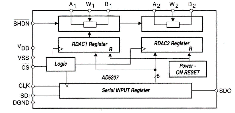
• AD5207: Device with two potentiometers on the same microchip. Available commercial values are 10 kohms, 50 kohms and 100 kohms. It uses an 8-bit word for the adjustment and therefore has 256 available positions. The block diagram of this family is shown in Figure 5.
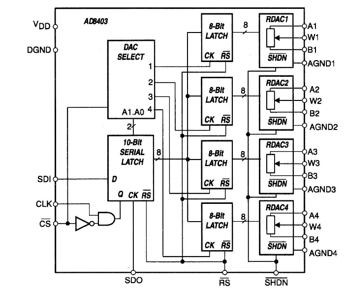
• AD8400, AD8402 e AD8403: Devices with one, two or four potentiometers on the same microchip. Available commercial values ??are 1 kohms, 10 kohms, 50 kohms and 100 kohms. They use an 8-bit word for adjustment and therefore have 256 available positions. The block diagram of this family is shown in Figure 6.
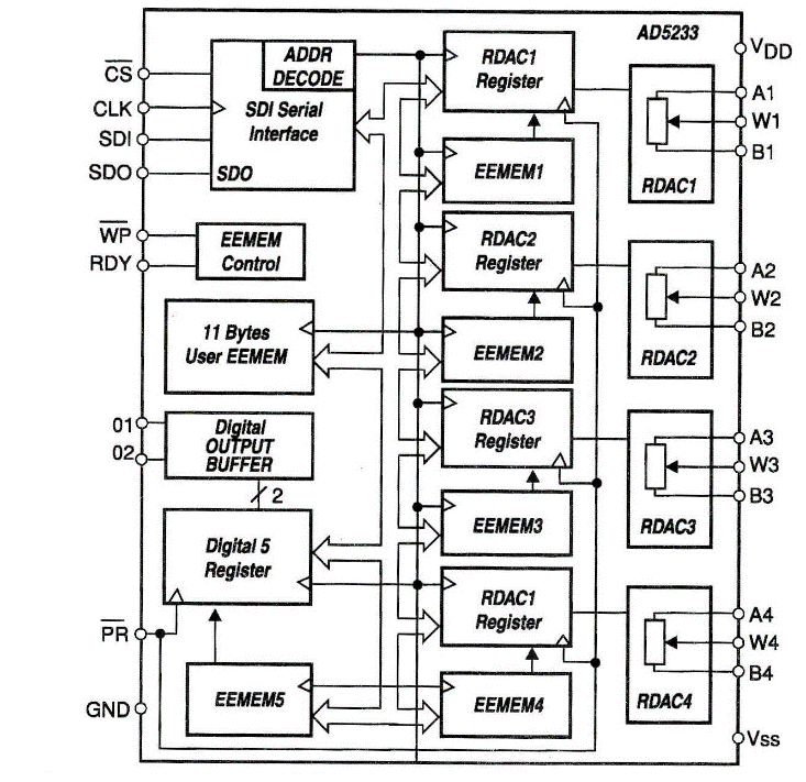
• AD5233: Device with four potentiometers on the same microchip. This one is interesting because it has a memory with 11 bytes of 6 bits for each potentiometer, which stores position values, thus allowing the possibility of restarting the operation in the same position as it was in the last execution. Available commercial values are 10 kohms, 50 kohms and 100 kohms. As it uses a 6-bit word for the adjustment, it has only 64 available positions. The block diagram of this family is given in Figure 7.
Dallas Semiconductor
Their devices have the same basic characteristics as Analog Devices' products, except for the supply voltages, which ranges from 3 to 5 V. The devices shown use an 8-bit word for adjustment and therefore have 256 available positions. Details are shown below.
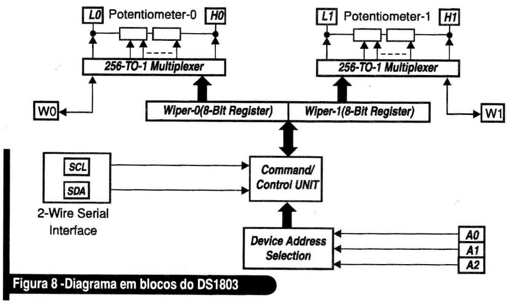
• DS1803: Device with two potentiometers on the same microchip. Available commercial values are 10 kohms, 50 kohms and 100 kohms. The block diagram of this family is shown in Figure 8.
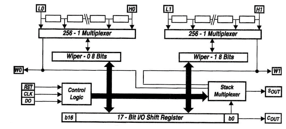
• DS1267: Device with two potentiometers on the same microchip. Available commercial values are 10 kohms, 50 kohms and 100 kohms. The block diagram of this family is illustrated in Figure 9.
Microchip
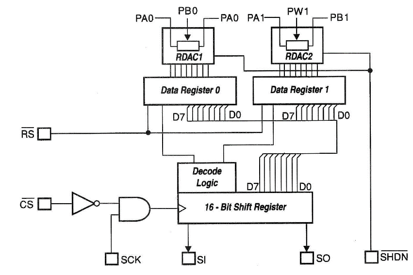
• MCP41XXX e MCP42XXX: Devices with one or two potentiometers on the same microchip. Available commercial values ??are 10 kohms, 50 kohms and 100 kohms. Position adjustment is handled via a three-wire serial interface. They use an 8-bit word for adjustment and therefore have 256 available positions. They work powered from 2.7 to 5.5 V and, when switched off, they have a current consumption of less than 1 µA. The block diagram of this family can be seen in Figure 10.
Maxim
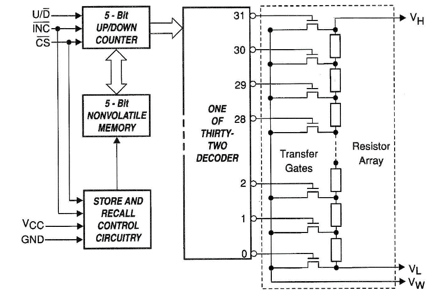
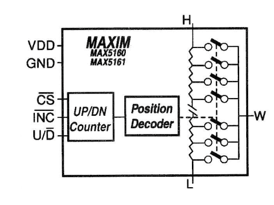
• MAX51 60 e MAX5161: Devices with only one potentiometer on the microchip. Available commercial values are 50 kohms, 100 kohms and 200 kohms. Position adjustment is made through an up/down counter. It uses a 5-bit word for the adjustment and therefore has only 32 positions available. They work from 2.7 to 5.5 V, and when switched off, they have a current consumption of less than 100 nA. The block diagram of this family is shown in Figure 11.
Xicor
• X9313: Devices with only one potentiometer on the microchip. They also have a memory that stores the current value before shutting down, making it possible to restart the operation in the same position it was before. Available commercial values are 1 kohms, 10 kohms, 50 kohms and 100 kohms. Position adjustment is made through an up/down counter. It uses a 5-bit word for the adjustment and therefore has only 32 positions available. They work from 3 to 5 V and, when switched off, have a current consumption of less than 500 µA. The block diagram of this family is shown in Figure 12.
Calculation and Adjustment of Resistance Values
What value will the device assume when turned on? To answer this question, we must recall the electrical scheme of an analogue potentiometer, shown in Figure 13. The resistance between terminals A and B will always be the nominal value of the device (typically 1 Kohms, 10 Kohms, 50 Kohms or 100 Kohms). The resistance value between the central terminal, W, and the ends will depend on the type of device you are using.
Those without internal memory, when turned on, will go to the central position (step 128 on a scale with 256 positions) and will remain there until they are adjusted to a new value. Those with memory will move the register to the value referring to the last used position.
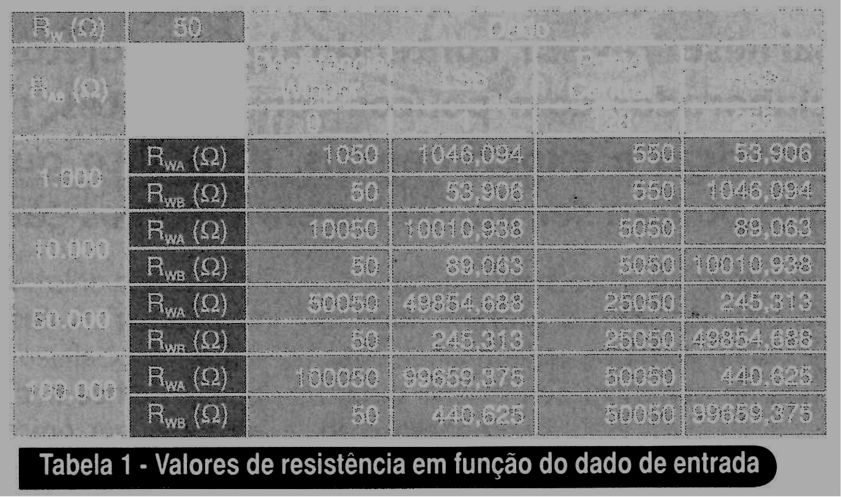
The central terminal (wiper) usually has a fixed resistance value, which must be included in the calculation. Equations 1 and 2 are used to find the resistance value, based on a device with 256 positions, where D is the value to be stored in the register. Table 1 shows the resistance obtained for the most common nominal values, considering the contact resistance (wiper) of 50 ohms and 256 steps. This table also shows the central value (position 128), where most digital potentiometers start.
Applications
The main applications in which digital potentiometers are widely used are:
• Volume Control: New audio equipment (MP3 players, CD players, midi systems, car stereo, etc.) no longer have the old volume adjustment knobs. Everything is achieved through digital keys. Some of these switches already make use of digital potentiometers to control the output volume.
• LCD Contrast Control: Look at your computer's LCD monitor. Did you find the contrast, brightness, colour, etc., settings? Internally, a digital potentiometer does the function of increasing or decreasing the values ??that will be adjusted on your screen.
• Automatic Gain Control: Many electronic circuits require AGCs, which are easily implementable through digital potentiometers.
• Programmable Filters, Delays and Time Constants: Imagine recalibrating a filter designed for a specific frequency using analogue potentiometers. With digital potentiometers, the values ??referring to each frequency can be stored in the memory, and a simple touch of a button adjusts the entire circuit. The same is valid for delay lines and constant voltage generators, used as reference.
• Voltage Adjustment in Power Supplies: Replace the old analogue potentiometers in generating a reference for the output voltage of the power supplies.
• Programmable Voltage-To-Current Conversion: The value to be converted is stored in a memory and transferred to the potentiometer when conversion is required.
• Sensor Calibration: As they generate well-known resistance values, they serve as sensor calibration elements.
Conclusion
Since more and more equipment tends to be micro-controlled or have a control logic, digital potentiometers tend to be much more advantageous. The robustness of the device, its lifetime and ease of programming outweigh the small range of available commercial values and the low power they can dissipate.

