Obs. This text was originally written by the author for a magazine in Brazil and after included in its boo book Robotics, Mechatronics and Artificial Intelligence.
Reversing a motor is a simple task using a relay with DPDT contacts. But the use of relays presents some inconveniences: relays are relatively expensive, some are large and heavy and they use mechanical parts that can fail.
In addition, it can be difficult to find models with the desired characteristics.
The use of transistors as switches offers the designer new resources for controlling dc loads. In this section we will show how to use transistorto this task.
But, unfortunately, reversing a motor in this way requires a DPDT switch, whereas a transistor operating as a switch is an SPST unit.
How do we solve this problem?
The solution is provided here. Two or four transistors can be installed together in some special configurations, allowing the control of a dc motor in the same manner as a DPDT switch.
Two special configurations are used for this task: the half bridge and the H-bridge or full-bridge as it is also called.
Let‘s see how they work and how can we use them in projects involving robotics and mechatronics.
The Half Bridge
Two batteries and two SPST switches are used in the circuit of Figure 1.
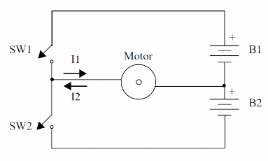
In normal operation, two conditions are possible:
1. If SW1 is closed, the current is supplied by B1 and the motor runs forward.
2. If SW2 is closed, the current flows across the motor in the opposite direction, now supplied by B2. and it runs backward.
It should be clear to the reader that having SW1 and SW2 Closed at the same time is a forbidden condition, as it causes the two batteries run in a short circuit.
Replacing the switches with transistors (bipolar or FET), we can control the motor by biasing the transistors from external voltage sources as shown by figure 2.
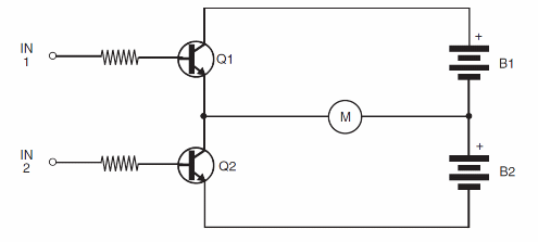
The polarity of the control voltage depends on the type of the transistor. NPN and P-channel power FETs are made conductive when positive voltages are applied to their bases or gates.
Alternatively, PNP transistors are made conductive when negative voltages are applied (or they are connected to ground).
The main disadvantage of this configuration (using only two transistors) is that we need a dual or symmetric power supply. This configuration increases the degree of complexity when designing the drive circuits.
The solution is given by a configuration using four transistors as shown next.
H-bridge or Full Bridge
Let‘s start from a basic circuit where we now use four SPST switches. as shown in Figure 3.
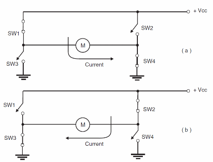
In operation, we can imagine two situations:
1. In Figure 3a. when we close SW1 and SW4, the current flows in one direction. and the motor runs forward.
2. In Figure3b, when we close SW2 and SW3, the current flows in the opposite direction. and the motor runs backward.
It is obvious that SW1 and SW3 can't be closed at the same time, since this procedure will cause a short in the batteries. For the same reason, SW2 and SW4 can't be closed at the same time.
Let‘s now replace the switches with bipolar or FET transistor as shown in Figure 4.
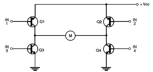
Depending on the bias, we can make the transistors act as switches, conducting or not conducting the current.
In this case, we also have the forbidden condition where Q1 and Q3 conduct, making the battery run in a short, and the same condition for Q2 and Q4.
To achieve proper control of this bridge, we have two possibilities:
1. We can directly excite the transistors from sensors, switches, or another circuit in a configuration that is “intelligent” enough to avoid the forbidden conditions.
2. We can add the “intelligent” configuration or logic to the bridge, thereby avoiding the forbidden states.
In the second case, the “intelligent” configuration depends on the type of transistors used. If using PNP and NPN transistors, for instance, it is enough to wire together the bases of each transistor pair, biasing them according to the direction the motor must run.
If we use only one type of transistor, NPN bipolar transistors or power MOSFET P-channel, inverters must be added to the circuit to provide the necessary logic to avoid forbidden conditions.
In all these cases, we can see that the signals must be applied to the transistor so that Q1 and Q3 don't conduct at the same time (likewise, Q2 and Q4).
These two possibilities bring us to several types of circuits for dc motor control with a half bridge or full bridge, depending on the signal sources or control voltage sources.
In Figure 5a, we have only one input, and the motor runs in one direction when the input is high (positive voltage).
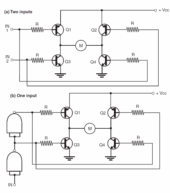
It runs in the opposite direction when the input is low (ground). Notice that this configuration can be made compatible with such logic devices as TTL and CMOS.
The other option, shown in figure 5b, uses two signal sources. In this case, we have four possibilities of operation, given in the following table:
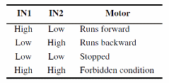
This combination of inputs can change according to the configuration whether we use only NPN transistors, only PNP transistors, or both NPN and PNP in the same bridge.
The practical circuits the reader can find in this section will show how the configurations can change.


