Note: This and other assemblies of the same kind the reader will find in the Electronic Projects from the Next Dimension – Book by Newton C. Braga.
What kind of power emanates from the people who say they are endowed with "paranormal" capacities? What kind of energy does the snow melt around the Tibetan monks in concentration on a cold morning or making objects on a table move without needing to be touched? No one knows if really these phenomena may be associated with some form of physical energy as science defines, but the researchers, perhaps even using a misnomer for what happens are track something that can be very real.
The ancient Hindus call this energy Prana; the old alchemists to cite as "vital fluid" while modern researchers call "bioplasma". However, the most widespread of all denominations to this form of expression is "psychokinetic" or abbreviated PK.
In principle it seems that all people are sources of this form of "energy" (*) strange which can be concentrated, diluted or directed according to our will, but only after some training. This "training" is what the monks, gurus and other mystics do in order to direct their efforts to master these demonstrations. Detecting these manifestations is a problem that the electronics can solve even if not known exactly.
But there is a fact associated with these manifestations that may contribute to its detection: in the states of concentration, meditation or relaxation its manifestation is associated with the person's body temperature variations. If we can not then detect this event directly (because we do not know its nature) we can do indirectly by temperature changes that it causes. This is one of the purposes of our device: a sensitive detector of changes of temperature, especially the tips of the fingers (where the greatest variations are believed to occur by the "emanation" of the phenomenon) and can be used in practice or experiences to help get the meditative states.
Another possibility is to replace the temperature sensors by electrodes to measure the conductivity of the skin and thus make possible verification of their change in various states of consciousness. These changes can also be used for other purposes such as, for example, in the detection of acupuncture points.
Finally, variations on the device may detect that allow use in other applications such as esoteric own telekinesis (movement controlled by the mind) using light or magnetic sensors.
HOW IT WORKS
The heart of our psychotronic detector is a silicon semiconductor diode which has characteristics that vary significantly with temperature. When biased in reverse such diodes exhibit a degree of conduction depending on the temperature.
What happens is that the leakage current called the reverse direction is increased by the presence of charge carriers that are released when the junction temperature rises. Thus, if a diode approach of our mouth and letting go one "puff" of hot air that will be enough to cause a significant change in its temperature and also its electrical conduction.
Similarly, if you approach the diode our fingers variations in temperature between the finger itself and the environment caused by some kind of unknown change, you may have result in a significant change of its electrical conductivity, as shown in Figure 1.

Even mentalizing a condition that we wish the LED to heat can cause this to occur which leads to an important component of the application in paranormal studies. To acknowledge the variations of this current flowing in the diode and is very weak, we need a special circuit.
The circuit used is an operational amplifier of very high gain. In this circuit we set the reference voltage at the inverting input through a setting potentiometer and the non-inverting input will call two diodes polarized in the opposite direction which will serve as temperature sensors.
When the conductivity of the diodes is such that the voltage at the noninverting input is equal to the voltage at the reference input in the output we have a voltage that is approximately half the supply voltage. As the indicating instrument is connected to a divider with two resistors fixing the other hand also the voltage at half the supply voltage no current flows at all, as shown in Figure 2.

However, if the temperature of the diodes to change more than the other, the voltage at non-inverting input will change and this can have in output a higher or lower voltage than half the power causing the needle instrument moves to one side or the other. The operational amplifier gain is large which means that a very small temperature change causes a great variation in the output voltage.
Turning a pot in the feedback circuit (P2) you can control the operational amplifier gain and thus its sensitivity. To use the device in the experiments we propose is necessary that the diodes are placed in a studied arrangement. What we do is to place the diodes in a box (which can also accommodate the device remaining two tubes where the person's fingers that focus should be tucked, as shown in Figure 3.
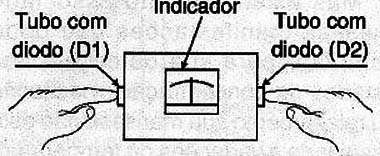
Thus, the diodes begin to undergo only the influence of temperature variations of the fingers and not the environment, such as air currents, direct sunlight, etc. Of course, for the effect to be detected without actually there is contact of the fingers with the diode must be small tube in a small retaining ring that prevents it, as shown in Figure 4.

Since the circuit can be powered by cells or battery, since its consumption is very low, it can be taken and used anywhere. In an application with conductivity sensors they can be formed by metal taps in which the researcher or researched to support your fingers. Or fine needle electrodes can be used as electrodes in the case of a sensitivity study to acupuncture points.
ASSEMBLY
In Figure 5 we have the complete diagram of psychotronic detector.

The arrangement of components on a printed circuit board is shown in figure 6.

The diode for the sensors can be of any type commonly used, but they must be equal. Types like the 1N4148 or 1N914 work well in this type of device.
The operational amplifier is a CA3140 but equivalent can be used.
The indicator instrument is a milliammeter of 50 - 0 - 50 µA zero center scale, of the type found as a battery status indicator in many older recorders and also amplifiers as balance indicators.
All resistors are 1 / 8W as indicated in the link material. The device is extremely low consumption which allows the use of fourth common small batteries or one nine volt battery for power.
TEST AND USE
Turn the unit's power and place initially P2 a medium strength position (half of the adjustment). Adjust then P1 to the instrument indicates zero (middle range).
Touching one of the diodes and the other the needle of the instrument should oscillate from one side to another. The touch should not be done in the diode terminals but the component body. Releasing a puff in either diode must be observed the same effect.
Once proven operation is only using the device. For this stick your fingers in the holes of the diodes and set P1 and P2 in order to have balance in the indicator instrument and the desired sensitivity. Then just try to concentrate and make it light the indicator to move to one side or the other.
Semiconductors:
CI-1 - CA3140 - Integrated circuit - operational amplifier
D1, D2 - 1N4148 - General purpose diodes - see text
Resistors (1 / 8W, 5%)
R1, R2 - 10 k Ω - brown, black, orange
R3, R4 - 22 k Ω - red, red, orange
R5 - 1 k Ω - brown, black, red
P1 - 1 M ohm
P2 - 470 k Ω
Capacitors:
C1 - 10 x 16 µF V - Electrolytic
Miscellaneous:
M1 - 50-0-50 µA - microamperimeter with zero at the center of the scale
S1 - Single switch
B1 - 6 or 9 V - 4 batteries or battery
Printed circuit board, Holder for assembly of batteries or battery connector support, wire, solder, etc.