
Many reports on the appearance of unidentified flying objects, such as recently occurred in the center of our country (Brazil) with great coverage by TV, include magnetic nature disorders, for example, the stop of car engines (possible by problems in the ignition system ), stoppage watches and breakdowns in the various systems that have sensitive electrical circuits.
Based on this fact, the magnetic field detectors or magnetic disturbances can be used as µFO detectors can sound an alarm or warning when the phenomenon occurs.
The circuit described here emits a short beep (the duration may be changed by assembler) when a sensing coil captures a perturbation magnetic nature, that is, a magnetic field contraction or expansion or moving.
The circuit is very sensitive and can be triggered even by a stronger electric discharge during a storm or by nearby electrical circuit closing, hence being particularly suitable for field research.
Powered by standard batteries, the device quiescent current is very low which allows it to be connected permanently without the danger of depleting the batteries quickly.
The audible signal sounds, on the other hand, is strong enough to warn people that are nearby.
CHARACTERISTICS
* Supply Voltage: 6 V
* Standby consumption: 2 mA (typ)
* Consumption with tone alarm: 50mA (typ)
HOW IT WORKS
The sensor is a pich-up coil formed by thousands of enameled wire turns very thin and which is connected in differential form a very sensitive operational amplifier.
The operational amplifier is of the type with field-effect transistor (FET) in the input and has the gain set to P1. Therefore, this component (P1) can serve to adjust the sensitivity avoiding shooting with ambient noise.
In the presence of any variable magnetic field, ie, in which the lines of force move the cutting of the loops by this field the coil generates a signal which is applied to the operational amplifier.
The signal is amplified and thus have the appearance operational output (pin 6) of a much higher voltage causes the transistor Q1 is brought to driving for a while, which causes C1 via the triggering of monostable 555.
What happens here is that the round for a second operational output of the high level causes the transistor to saturation which grounds the capacitor C1 and thus applies to pin 2 of the 555 a low level signal necessary to trigger it on.
With the trigger pulse, the output of the monostable 555 goes to high level for a time interval which depends on the values of R5 and C2. The capacitor C2 must be chosen to provide a longer tone as the reader needs for their application. Values between 220 µF 22 nF and can be used without problems.
In the high level, the output 555 biases the base of transistor Q2 which is one of two transistors forming a signaling audio oscillator. The frequency of this oscillator and therefore the tone emitted depends R6 and C3. These components may also be made changes according to the desired shade.
In the project, the tone is fixed, but the resistor R6 can be replaced by a trimpot 100 k Ω with a resistor of 10 k Ω in series to adjust the tone. We can then set the tone in the trimpot.
The signal generated by this oscillator is applied to a small speaker that reproduces.
ASSEMBLY
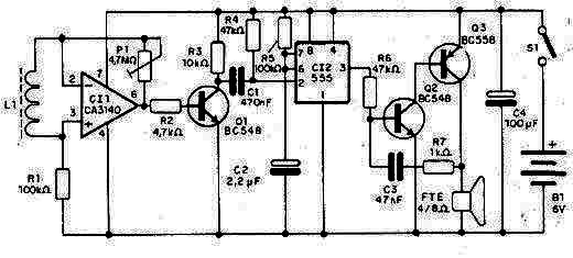
In Figure 1 we have the complete diagram of the µFO Detector.
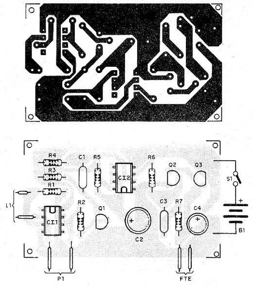
The components can be mounted on a small printed circuit board that fits into a very compact plastic case, as shown in Figure 2.
The most important component of this project is the L1 coil, because it determines the device's efficiency.
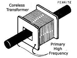
A simple solution is to use the primary winding of an output transformer of old valves radio at least with 10,000 ohm impedance, or even a common pich-up transformer primary 220 V or 110 V which has a laminated core and put in its place a ferrite rod, as shown in figure 3.
The connections of the transformer to the circuit input must be short and well shielded so electrical noise are no longer obtained that the circuit is intended to capture magnetic disturbances. The pich-up transducer may be protected by a piece of foil to be connected to the negative source so as to function as electric shielding. Thus, the circuit only pick-up magnetic disturbances.
Another possibility of having the sensor consists of at least curl 10, 000 turns of very fine enamelled wire on a ferrite rod and then wrap it in foil to form electrical shielding.
Without the electrical shielding, radio signals from local stations or radio interference pulses that occur in electrical installations with the opening and closing of circuits can trigger the detector.
For the placement of integrated circuits, we suggest the use of DIL sockets.
The resistors are all 1/8 W 5% or more of tolerance and electrolytic capacitors must have 6V operating voltage or more. The capacitors C1 and C3 may be ceramic or polyester. The transistors admit equivalents.
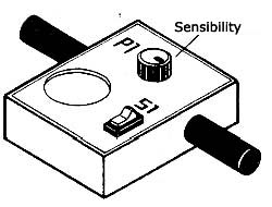
The fit together in a plastic box of small dimensions as shown in Figure 4.
The speaker has 5 cm with 8 Ω impedance. Other sizes can be used, adapting it to the size of the box.
TEST AND USE
The operating test is simple: connect S1 and go slowly increasing the resistance of P1 (gain) until there is a touch of alarm. Go back a bit P1 until the threshold of triggering.
Passing a small permanent magnet quickly near L1 the alarm should produce a short tone.
To use the device just leave it on away from electrical appliances or power grids. A touch indicates the capture of a disturbance magnetic nature.
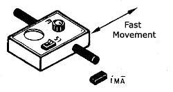
To detect magnetic fields quickly pass the device on the target site, as shown in Figure 5.
This unit can be used to detect the presence of hidden magnets in alarms and other devices magnetic drive systems.
Strong magnetic fields such as those caused by domestic electrical appliances, and that according to studies can be harmful to health can be detected by this device.
Semiconductors:
CI-1 - CA3140 - Integrated circuit
IC-2 - 555 - IC
Q1, Q2 - BC548 or equivalent – NPN general purpose transistors
Q3 - BC558 or equivalent - PNP general purpose transistor
Resistors (1 / 8W, 5%)
R1 - 100k Ω
R2 - 4.7 k Ω
R3 - 10k Ω
R4 - 47 k Ω
R5 - 100k Ω
R6 - 47 k Ω
R7 - 1 k Ω
P1 - 4.7 M Ω - trimpot
Capacitors:
C1 - 470 nF - ceramic or polyester
C2 - 2.2 µF x 6V or more - Electrolytic
C3 - 47 nF - ceramic or polyester
C4 - 6V x 100 µF or more - Electrolytic
Miscellaneous:
L1 – pich up coil - see text
FTE - 8 Ω x 5 cm - speaker
S1 - SPST switch
B1 - 6V - 4 small batteries
Printed circuit board, ferrite rod, support for 4 small batteries, plastic box for assembly, foil, wire, solder, etc.


