
The mysteries of the human mind studied with the help of electronic circuits open doors to a fascinating field of work for many researchers.
Of course, we cannot just plug a pair of electrodes to a person and connect them to a frequency meter, oscilloscope or computer so that we can easily discover what is going on inside one’s body and much less in one’s mind.
Besides the possibility of applying hazardous voltages to the individual, we need to know what type of signal can be captured and how we can process them in order to analyze him/her with a common electronic circuit.
One of the simplest methods and interesting to be integrated or interface something electronic with a person, and thus enable the realization of interesting experiences, is the biofeedback.
The most interesting in the biofeedback use is that, besides being possible to make its interfacing with the research devices, the individual himself/herself being studied can control the experiment.
It is this possibility that we intend to bring to our readers who are interested in this subject.
Certainly in addition to the experiments involving people such as those related to relaxation, hypnosis, transcendental meditation, parapsychology, ESP (Extra Sensory Perception) and even ITC (Instrumental Trans Communication) we can also program works involving animals or plants. Experiments with circadian rhythm alterations can easily be made using the same circuits employed in the study of alpha rhythms and even biofeedback.
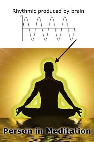
Here is offered to the reader in this article few simple biofeedback circuits that enable the reader to control a lamp or an external circuit or even send signals to a computer at a speed approaching the alpha rhythm and thus obtain relaxation almost complete as suggested in Figure 1.
WHAT IS THE BIOFEEDBACK
The emotional and physical states of a person also produce the manifestation of electrical phenomena. The contraction of a muscle, the concentration in a more difficult task or even the relaxation and sleep are responsible for the emergence of voltages and even signals with fixed frequencies.
These voltages can be detected with the connection electrodes on the skin with the assistance of very sensitive amplifier circuits.
In the case of mental activities were detected certain signals which have very well-defined frequencies and are associated to specific emotional states.
These signals associated to rhythms are basically three which have the following frequency ranges:
Delta rhythm: from 0.5 to 4 Hz - state of consciousness
Theta rhythm: from 3.9 to 7.9 Hz - deep sleep
Alpha rhythm: from 7.9 to 13 Hz - aware - awake but without paying attention to anything
Beta rhythm: from 13 to 20 Hz - aware but paying attention to the outside world
Specifically the alpha rhythm can be very interesting to the relaxation, as we can see.
If we make a person self-induce him/her to produce signals at this rate what happens is that he/she will be brought to a state of alert or awakeness, but without paying attention to anything, in other words, relaxed.
A simple way to achieve this with the help of machines is to produce stimulus in this frequency range.
The biofeedback does just that.
An electronic biofeedback circuit is basically formed by an input circuit which can receive stimulus or a person commands and in its function some type of transducer is driven to feed back with some sort of signal from the person who operates, as shown Figure 2.
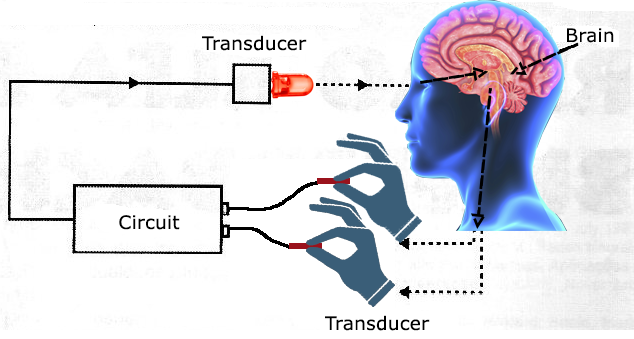
Thus, in the system illustrated in Figure 2, the electrical impulses generated by the hand motion which has the electrodes generates lamp light variations.
Seeing these changes one must move his/her hands in order to obtain a certain brightness.
In Figure 3 we have an experience made with a plant in which an electrode placed on one of its leaves captures the small electric potential generated by its cells. This potential is taken to a circuit and amplified so as to control the brightness, frequency or both of a common lamp.
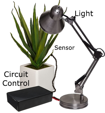
The experiment is to determine which is the brightness and frequency that the plant adjusts by feedback in order to get what it would be a “pleasant” balance.
We can see how variations from the daylight to the night light associated with these stimulus or other stimulus alter its circadian rhythm.
See then the fact that there is a closed circuit for the signals, where one part is obtained from the electric sensors and the other part of the route is made by transducer signals which can be light, sound or another energy form feature the biofeedback.
THE PROJECTS
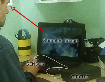
For readers who wish to experiment, especially involving stimulus in the range of low frequencies go from delta to beta rhythms we give three quite interesting circuits, one of which can even be attached to a computer.
Their signals in digital form can be read by the parallel port and through an appropriate program can generate images or sound on the screen that will consist in stimulating the relaxation or what you might desire to produce, as shown in Figure 4.
Circuit 1 - Simple Biofeedback - LED Pulsing
The basic purpose of this project is to bring researcher to a state of relaxation or even to produce the research on the mental state changes which can be monitored by changes in the frequency from the two blinking LEDs.
The circuit is nothing more than a low frequency oscillator which can be tuned to operate between 0.5 and 30 Hz (corresponding to the searched rhythms) controlled by the action on the three electrodes.
The electrodes may be attached to the skin or it can simply cause the researcher to support the fingers over them, controlling the pressure to obtain the relaxation or the desired condition.
In this case the relaxation will be obtained when by the finger pressure the operator is able to adjust the frequency of the LEDs so that it coincides with his/her own alpha rhythm.
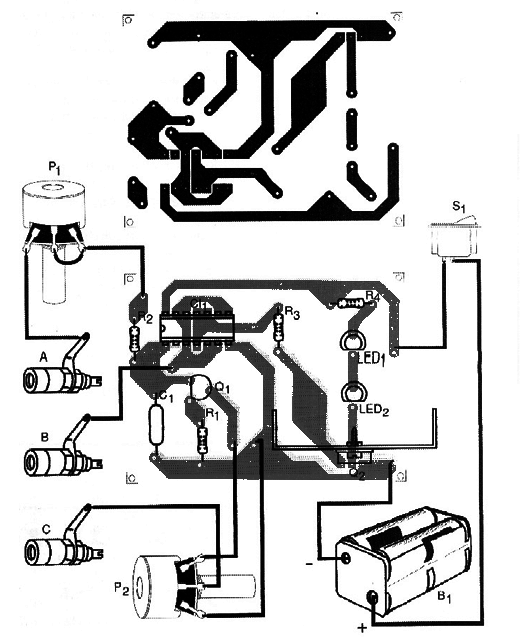
In Figure 5 we have the complete circuit of the visual biofeedback that is very simple by the amount of components used. The printed circuit board assembly for this is shown in Figure 6.
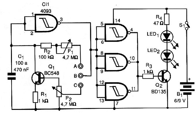
If there are two LED indicators being used, the transistor Q2 may be a BC548, but if the player wants feed lamps with higher power in a system to operate an illuminator in the place, like in a room, can change the transistor Q2 for a BD135 and the LEDs together with a R4 for a lamp up to 500 mA.
In this case the transistor must be in a heat radiator and the circuit must be powered by an external power supply.
The electrode consists of three metal flat pieces (which can be three coppery regions of a printed circuit board) which are connected to the circuit by wires that should not be more than half a meter long. The high impedance of the circuit makes it very sensitive to capture hum.
The circuit has two settings: frequency and sensitivity which must be made experimentally according to the skin conductivity of the researcher’s fingers that can vary greatly depending on several factors.
The circuit can be powered by four small batteries or one 9-volt battery and instead of two LEDs, if the reader may prefer, use only one.
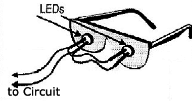
One interesting possibility resulting from the use of two LEDs consist on the assembly of relaxing glasses, shown in Figure 7.
Note: This tool should never be used in people with epilepsy.
The circuit can be contained in a small plastic box and its use is very simple.
THE USE
The person doing the research must support three fingers of one hand on the electrodes and then with the other hand adjust the two controls (P1 and P2) so that the blinking of the LEDs are on the same pace desired to be induced.
For example, for the alpha rhythm you adjust these controls so that the LEDs produce between 4 and 7 flashes per second.
Then, by controlling the pressure of the fingers on the LEDs the researcher should try to modify the speed of flashes so that it is at a frequency that seems pleasant or mild to relaxation. Experiments by changing the capacitor C1 can be made if this condition becomes difficult to achieve.
Semiconductors:
CI-1-4093 - CMOS integrated circuit
Q1 - BC548 or equivalent - NPN transistor for general purposes
Q2 - BC548 or BD135 - NPN transistor - see text
LED1, LED2 - Common LEDs of any color
Resistors (1/8 W, 5%)
R1, R3 - 1 k ohm
R2 - 100 k Ω
P1, P2 - 4.4 M Ω - Pots
Capacitor:
C1 - 100 nF to 470 nF - Ceramic or polyester
Miscellaneous:
S1 - SPST switch
B1 - 6 or 9 V - 4 AA cells or a battery
Printed circuit board, a box for the assembly, electrodes, wires, welding, buttons for the pots, etc.
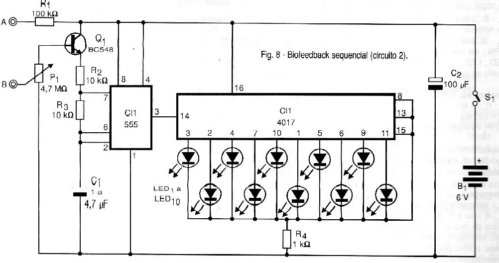
Circuit 2 - The Sequential Biofeedback
The basic idea of this circuit is to trigger a sequence of 10 LEDs at a speed which should be controlled by the finger pressure on an electrode or by the voltage obtained from electrodes placed on the skin, in plants, etc.
The only adjustment is of sensitivity, but there may be added a basic frequency control which consists of a 1 M ohm potentiometer between the collector and the emitter of Q1.
In Figure 8 we have the complete diagram of this biofeedback.
The arrangement of the components on a printed circuit board is shown in Figure 9.
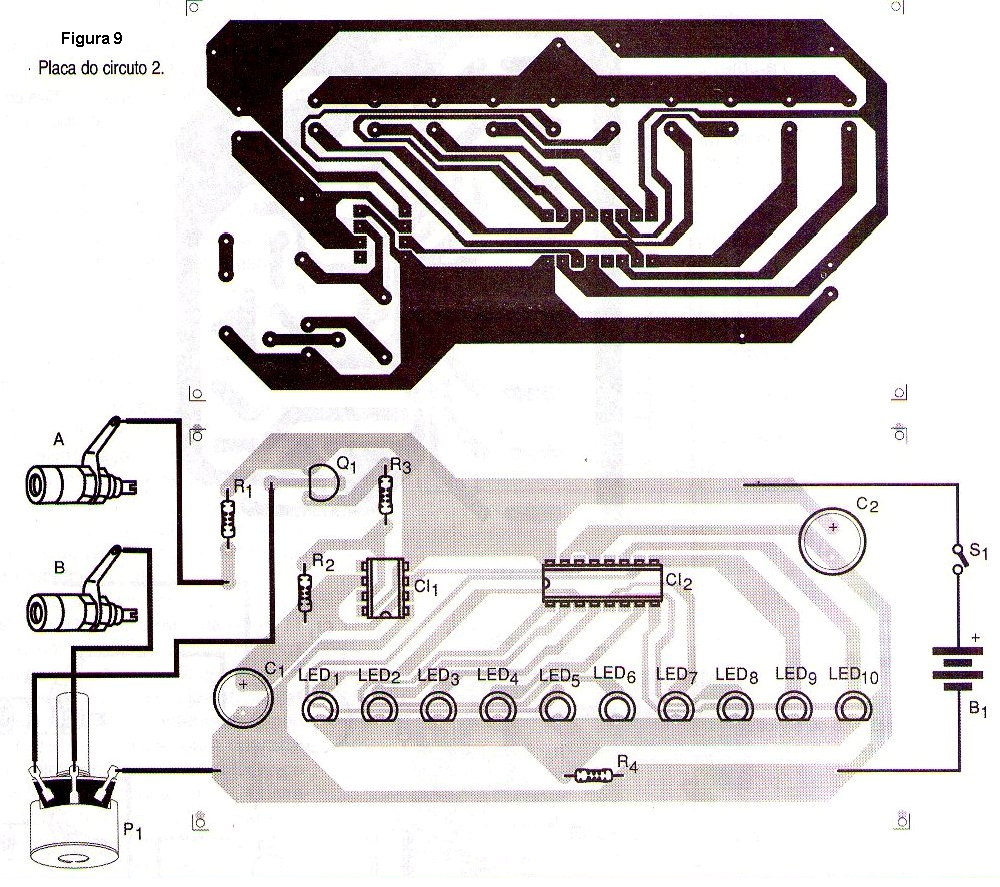
It is powered by 4 ordinary AA cells and the assembly can be installed in a plastic box. The electrodes for the operation with the fingers pressure may be the same as suggested in the previous assembly with the difference that in this case we have only two metal pieces.
THE USE
Support your fingers on the electrodes and adjust P1 until the LEDs start to run at a frequency that corresponds to the desired rate, for example from 4 to 7 times a second to the alpha rhythm.
If you cannot get the desired frequency range change the value of C1 to 220 nF or 10 µF.
Then try to control the speed of the LEDs by pressure watching them with concentration to get complete relaxation.
For experiments with plants or other beings that require greater input sensitivity use a 10 M ohm pot and eventually connect two transistors in Darlington configuration.
Semiconductors:
CI-1 - 555 - Integrated circuit
CI-2 - 4017 - Integrated circuit
Q1 - BC548 - NPN transistor for general purposes
LED1 to LED10 - Common LEDs of any color
Resistors (1/8 W, 5%)
R1 – 100 k Ω
R2, R3 – 10 k Ω
R4 – 1 k ohm
P1 - 4.7 M Ω - Pot
Capacitors:
C1 - 1 to 4.7 µF/12 V - Electrolytic
C2 - 100 µF/12 V - Electrolytic
Miscellaneous:
S1 - A simple switch
B1 - 6 V - 4 AA cells
A printed circuit board, a box for the assembly, electrodes, wires, buttons for the pots, etc.
Circuit 3 - The digital biofeedback - With PC Interface
Our third design is presented in two versions: the first drives a LED set in a way that its ignition represents a digital value from 0 to 256, i.e., 8-digit binary while the second applies binary values from 0 to 256 on the PC parallel port in a way to control a feedback program.
The two circuits are based on the A/D converter (Analogue-Digital ADC0804) by the National which is characterized by a good operation speed and 8 bit output of 256 possible binary values).
The first circuit, driving LEDs is shown in Figure 10.
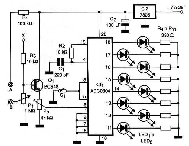
The binary value presented by the LEDs will depend on the fingers pressure on the electrodes connected between A and B. The sampling rate depends on C1 and R2 as the operating range is set for both P1 and P1.
The S1 switch is used to stop the sampling, if the reader wishes to have a value indication at some point.
The power can be taken from an external source from 7 to 25 volts, and as the circuit needs as few milliamps, the voltage regulator integrated circuit used does not need a heat radiator.
The printed board circuit for this circuit is shown in Figure 11.
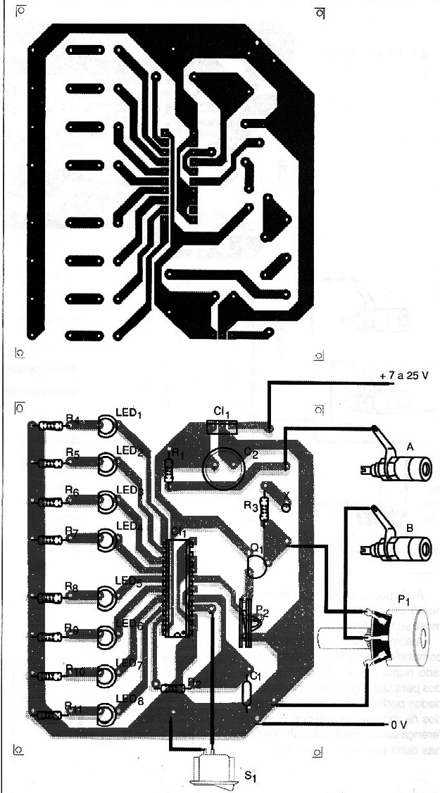
The set fits easily in a small box with the source and the electrodes are of the same type used in the previous projects. The X point may be used for the operation with a triple electrode, if the reader desires.
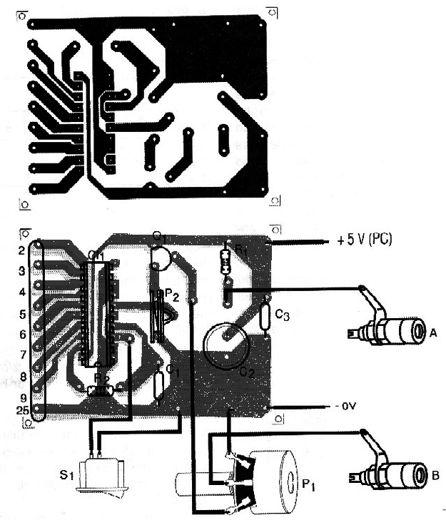
For the second version, shown in Figure 12 we have coupling to the parallel port made by a connector of 25 suitable pins.
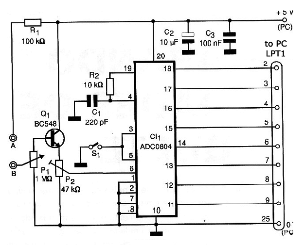
The power of 5 volts can be removed from the computer itself that it will work as its consumption, being is low, should not cause any overcharge to the source.
In Figure 13 we have the printed circuit board used in this design.
The capture program and data treatment can be done in QuickBasic, Visual Basic or Delphi, depending only on the imagination of each reader determine what it should produce in terms of acoustic or visual feedback.
a) Design with LEDs
Semiconductors:
CI-1 - ADC0804 - An analog-digital converter - Integrated circuit
CI-2-7805 - A voltage regulator - Integrated circuit
Q1 - BC548 or equivalent - A NPN transistor for general purposes
LED1 to LED8 - Common red LEDs
Resistors (1/8 W, 5%)
R1 - 100 k Ω
R2, R3 - 10 k Ω
R 4 to R 11 - 330 Ω
P1 - 1 M ohm - A pot
P2 - 47 k Ω - A pot
Capacitors:
C1 - 220 pF - ceramic or styroflex
C2 - 100 µF / 6V - Electrolytic
Miscellaneous:
S1 - A simple switch
A printed circuit board, electrodes, a box for the assembly, wires, welding, etc.
b) PC Interface Design
Semiconductors:
CI-1 - ADC0804 - A/D converter - Integrated circuit
Q1 - BC548 - A NPN transistor for general purposes
Resistors (1/8W, 5%)
R1 – 100 k Ω
R2 – 10k Ω
P1 - 1 M ohm - A pot
P2 - 47 k Ω - A pot
Capacitors:
C1 - 220 pF - styroflex or ceramic
C2 - 10 µF / 12 V - Electrolytic
C3 - 100 nF - Ceramic
Miscellaneous:
A printed circuit board, a box for the assembly, a connector for the PC parallel port, electrodes, buttons for the pots, wires, welding, etc.


