The important circuit to be suggested is the white noise generator shown in Fig. 1. This circuit will produce an electric signal Without a definite frequency.
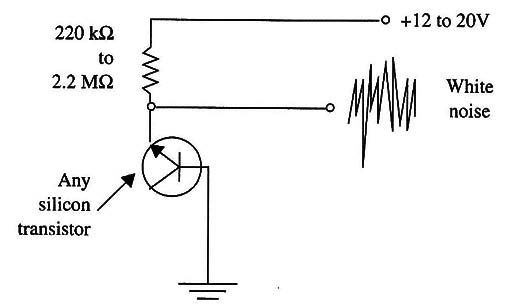
When amplified and used with an earphone or loudspeaker (Via an amplifier), the electric noise will produce an audible White noise. Note that White noise can be defined both as electric signals and mechanical vibrations in the audible spectrum.
How It Works
The thermal noise in a semiconductor junction (Q1) is amplified by the circuit and can be used as carrier or background noise source in the experiments.
As a thermal source of white noise we can use any silicon diode such as the 1N4l48 or 1N914, or the junction of any silicon general-purpose NPN transistor such as the 2N2222, BC547, BC548, 2N3904, etc.
Closing switch (S1) you can change the dynamic range of the noise, transforming the circuit into a “pink noise” generator. As mentioned earlier, the difference between the two kinds of noise is that white noise has a constant amplitude along its frequency spectrum, whereas pink noise has an amplitude that decreases with frequency.
Transistor Q2 is used to increase the amplitude of the noise acting as an amplifier. The gain is determined by R3 and R4.
Assembly
The circuit is not critical. You can mount it on a printed circuit board, a terminal strip, or even a solderless board. This circuit is shown by figure 2.
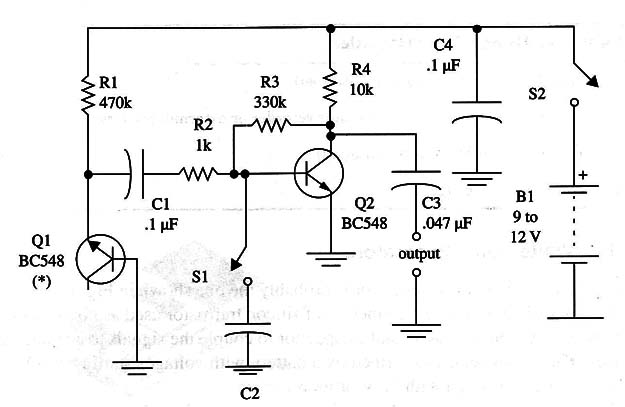
Figure 3 shows the layout of a printed circuit board that can be used to mount this circuit.
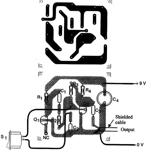
The only precaution you must take is with the output cable. You may use a shielded cable with a plug that matches the input jack of your tape recorder or amplifier.
If long cables or improperly shielded cables are used, the circuit can pick up hum (60 Hz from the ac power line), affecting the results.
The power supply can be a 9 V cell or eight AA (12 V) cells. The best results are usually obtained with a 12 V power supply, depending on the transistor used as the noise source. You can use two four-cell battery holders wired in series to obtain a 12 V source.
Using the Circuit
The white noise generator can be plugged to the input of any audio amplifier as shown in Fig. 4.
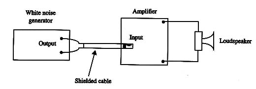
Another possibility is to plug the circuit to the input of a tape recorder, transferring the signals directly to the circuit.
In paranormal research, recording voices (Instrumental Transcommunication – see my book Electronic Projects from the Next Dimension), in the case of the tape recorder, record on virgin tape with the circuit plugged into the microphone input. Rewind the tape, and then try to hear some sounds mixed with the white noise.
Remember that the sounds or voices are very weak and sporadic. It is necessary to be patient, and many hours of recording are necessary to find something interesting. Refer to the experimental procedures outlined at the beginning of this section. The use of a headphone can be interesting and helpful when trying to find some voices on the tape.
In the case of the amplifier, the circuit can be used to fill an ambient with white noise, reproduced by a common loudspeaker.
Although the suggested circuit is powered from a 9 V battery or 8 AA cells, the reader can also use a power supply such as the one shown in Fig. 5.
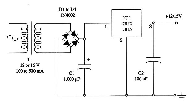
Any small transformer with a secondary winding rated to currents from 100 to 500 mA and voltages between 12 and 15 V can be used. Take care when using this circuit to avoid shock hazards, as it is plugged directly to the ac power line.
IC1 is not critical, as the circuit can be powered from a wide range of voltages.
So, for IC1 you can use the 7812 or 7815. The suffix indicates the output voltage.
For instance, the 7812 gives an output of 12 V. This component doesn’t need a heatsink, as current drain is very low when powering this circuit.
Important:
When using the power supply the circuit becomes more sensitive to the “hum” of the ac power line. This hum is a 60 Hz signal that can cover up the white noise as well as the voices, compromising the experiments. First ensure that the shield is solidly connected to the ground of the circuit (0 V point).
There are several ways to reduce or eliminate the hum, as follows:
1. Keep the cable between the white noise generator and the amplifier or tape recorder short.
2. Invert the position of the power supply plug (i.e., flip it 180° and plug it into the ac power line again).
3. Power the tape recorder from cells rather than the ac power line or use a
higher quality power supply for the tape recorder.
4. Move the equipment to locations far from the sources of hum, which include the wiring of your home and household appliances such as refrigerators, microwave ovens, fans, etc.
You can also use a hum filter between the input circuit and the tape recorder or the amplifier. One of our projects is a noise filter that can be tuned to 50 or 60 Hz (In some countries, the ac power line uses a 50 Hz current.)
Suggestions
Change R1 within the range of 220 k Ω to 1.2 M Ω) to get the better performance according to the semiconductor (Q1) used as white noise source.
Vary C2 in the range between 1,200 pF and 0.1 µF to alter the dynamic range of the pink noise.
R3 can be changed within a range between 330 k!) and 1.2 M9 to alter the gain of the transistor. Place in series with C2 a 100 kQ potentiometer.
Place in series with C2 a 100 kg potentiometer. You can use this potentiometer to control the dynamic range when the circuit is producing pink noise.
For the Circuit
Semiconductors
Q1 - BC548, 2N3904, or any transistor, or even a silicon diode (see text)
Q2 - BC548, 2N3904 or 2N2222, general-purpose NPN silicon transistor
Resistors
R1 - 470 k Ω, 1/8 W, 5%-yellow, violet, yellow (see text)
R2 - 1k9, 1/8 W, 5%-brown, black, red
R3 - 330 k Ω, 1/8 W, 5%-orange, orange, yellow
R4 - 10 k Ω, 1/8 W, 5%-brown, black, orange
Capacitors
C1 C4 - 0.1 µF, ceramic or polyester
C2 - 0.022 µF, ceramic or polyester (see text)
C3 0047 pF, ceramic or polyester
Miscellaneous
S1, S2 - SPST, toggle or slide switch
B1- 9 V battery, 8 AA cells, or power supply (see text)
Printed circuit board or solderless board, plastic box, battery clip, shielded cable, plug according to the input of the tape recorder or amplifier, Wires, solder, etc.
Power Supply
IC1 - 7812 or 7815, voltage regulator, integrated circuit (see text)
D1 to D4 - 1N4002 or equivalent, silicon rectifier diodes
Capacitors
C1 - 1,000 µF, 16 or 25 WVdc, electrolytic
C2 - 100 µF, 16 WVdc, electrolytic
Miscellaneous
T1 - 12 to 15 V, 100 to 500 mA secondary, transformer
Plastic box, power cord, Wires, solder, etc.


