
The mysteries of the human mind studied with the help of electronic circuits open doors to a fascinating field of work for many researchers.
Obviously, it is not enough to connect a pair of electrodes to a person and connect it to a frequency meter, oscilloscope or even a computer, so that we can easily discover what goes on inside someone’s body, let alone someone’s mind.
In addition to the possibility of applying dangerous voltages to the individual, it is necessary to know what type of signal can be captured and how we should process them to be able to do the analysis with a common electronic circuit.
One of the most simple and interesting methods of integrating or interfacing something electronic with a person enabling the realization of interesting experiences is the us the use of biofeedback.
The most interesting in the use of biofeedback is that, besides being possible to interface with the research devices, the individual being studied can control the experience.
It is precisely this possibility that we intend to take to our readers who are interested in the subject.
Of course, in addition to experiences involving people such as relaxation, hypnosis, transcendental meditation, parapsychology, ESP (Extra Sensory Perception) and even ITC (Instrumental Transcommunication) we can also program work involving animals or plants. Experiments with circadian rhythm disorders can be easily done using the same circuits used in the study of alpha rhythms and even biofeedback.
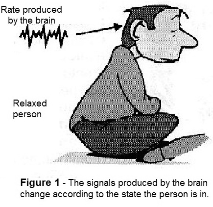
We offer the reader, in this article, some simple biofeedback circuits which allow the reader to control a lamp, or even an external circuit, or send signals to a computer at a speed that is close to the alpha rhythm and thus achieve almost total relaxation, as suggested in Figure 1.
WHAT IS BIOFEEDBACK?
The emotional and physical states of a person also produce the manifestation of electrical phenomena. The contraction of a muscle, concentration on a more difficult task or relaxation and sleep are responsible for the appearance of tensions and even signs with fixed frequencies.
These voltages can be detected by attaching electrodes to the skin and with the aid of very sensitive amplifier circuits.
In the case of mental activities, certain signals have been detected that have very well determined frequencies and are associated with specific emotional states.
These signals associated with rhythms are basically three which have the following frequency bands:
Delta rhythm: from 0.5 to 4 Hz - state of consciousness
Rheta rhythm: from 3.9 to 7.9 Hz - deep sleep
Alpha rhythm: from 7.9 to 13 Hz - alert - awake, but not paying attention to anything
Beta rhythm: 13 to 20 Hz - alert but attentive to the outside world
Specifically, the alpha rhythm can be very interesting for relaxation as we can see.
If we make a person self-induce to produce signals at this rate, what happens is that they will be brought to a state of alertness or awake, but without paying attention to anything, that is, relaxed.
A simple way to achieve this with the help of handsets is to produce stimuli in this frequency range.
Biofeedback does just that.
An electronic biofeedback circuit is basically formed by an input circuit which can receive stimuli or even commands from a person and some type of transducer is triggered in its function so as to feed back the person who operates it with some type of signal, as shown Figure 2.
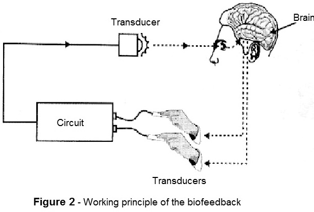
Thus, in the system shown in Figure 2, the electrical impulses generated by the hand moving the electrodes generate variations in brightness in a lamp. By seeing these variations, the person must move their hands in order to obtain a certain luminosity.
In Figure 3, we have an experiment made with a plant in which an electrode placed in one of its leaves captures the small electric potential generated by its cells. This potential is brought to a circuit and amplified in order to control the brightness, frequency or both of a common lamp.
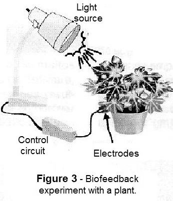
The experiment consists of determining what brightness and frequency the plant adjusts by feedback so as to obtain what would be a "nice" balance.
We can see how the light variations from day to night associated with these stimuli or other stimuli alter their circadian rhythm.
See, then, that the fact that there is a closed circuit for signals where one part is obtained from electric sensors and the other part of the way is made by signals from transducers which can be of light, sound or another form of energy, characterize the biofeedback.
THE DESIGNS
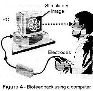
For readers wishing to experiment, mainly involving stimuli in the low frequency range from delta to beta rhythm, we give three interesting circuits, one of which can even be coupled to a computer.
Its signals in digital form can be read by the parallel port and through an appropriate program can be generated images or sound on the screen that will consist of the stimulus to the relaxation or to what is desired to do, as shown in Figure 4.
Circuit 1 - Simple Biofeedback with Pulsing LEDs
The basic purpose of this design is to take the respondent to a state of relaxation or to do research with the changes of mental state which can be monitored by the frequency variations of the flashes from two LEDs.
The circuit is nothing more than a low frequency oscillator, which can be adjusted to operate between 0.5 and 30 Hz (which corresponds to the searched rhythms) controlled by the action on three electrodes.
The electrodes may be fixed to the skin or the subject may simply have them placed to support the fingers, controlling the pressure in order to obtain relaxation or the desired condition.
In this case, relaxation will be achieved when the operator can adjust the frequency of the LEDs to match their own alpha rhythm.
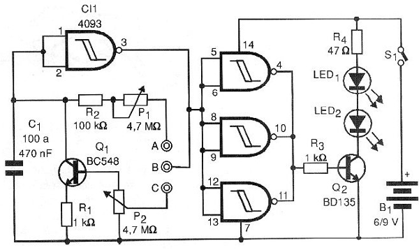
In Figure 5, we have the complete visual biofeedback circuit which is quite simple by the amount of components used.
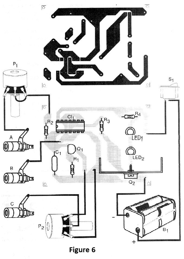
The printed circuit board for this assembly is shown in Figure 6.
If two indicator LEDs are used, the transistor Q2 may be a BC548, but if the reader wants to power lamps with higher power in a system to operate lighting a place, for example a room, one can exchange the transistor Q2 for a BD135 and the LEDs along with R4 for a lamp of up to 500 mA. In this case, the transistor must be in a heat radiator and the circuit must be powered by a source.
The electrode consists of three metal plugs (which may be three regions covered by a printed circuit board) which are connected to the circuit by wires that should not be more than half a meter in length. The high impedance of the circuit makes it quite sensitive to pick up some buzz or noise.
The circuit has two adjustments: frequency and sensitivity which must be done experimentally according to the conductivity of the finger skin of the respondent which can vary greatly depending on several factors.
The circuit can be powered by 4 small batteries or a 9 volt battery and instead of two LEDs, if you prefer, you can only use one.
An interesting possibility coming from the use of two LEDs is an assembly in a relaxation goggles, shown in Figure 7.
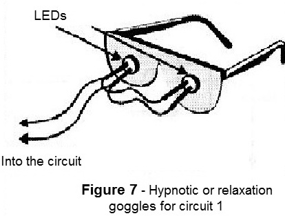
The circuit can be enclosed in a small plastic box and its use is very simple.
USE
The person studied should support three fingers of one hand on the electrodes and then with the other hand adjust the two controls (P1 and P2) so that the LED blinks are in the same rhythm as one wishes to induce.
For example, for the alpha rhythm, these controls are set so that the LEDs produce between 4 and 7 flashes per second.
Then, by controlling the pressure of the fingers on the LEDs, the respondent should try to modify the speed of the blinks so that it stays at a frequency that seems pleasant or that leads to relaxation. Experiments changing capacitor C1 can be made if this condition becomes difficult to achieve.
Semiconductors:
CI-1 - 4093 - CMOS integrated circuit
Q1 - BC548 or equivalent - NPN general purpose transistor
Q2 - BC548 or BD135 - NPN transistor - see text
LED1, LED2 - Common LEDs of any color
Resistors: (1/8W, 5%)
R1, R3 - 1k ohms
R2 - 100k ohms
P1, P2 - 4.4 M ohms - potentiometers
Capacitor:
C1 - 100nF to 470nF - ceramic or polyester
Miscellaneous:
S1 - Single switch
B1 - 6 or 9V - 4 batteries or a battery
Printed circuit board, mounting box, electrodes, wires, welding, buttons for potentiometers, etc.
Circuit 2 - Sequential Biofeedback
The basic idea of this circuit is to activate a sequence of 10 LEDs with speed that must be controlled by the pressure of the fingers on an electrode or by the voltage that is obtained from electrodes fixed to the skin, plants, etc.
The only adjustment is of sensitivity, but a basic frequency control consisting of a potentiometer of 1 M ohms, between the collector and the emitter of Q1, can be added.
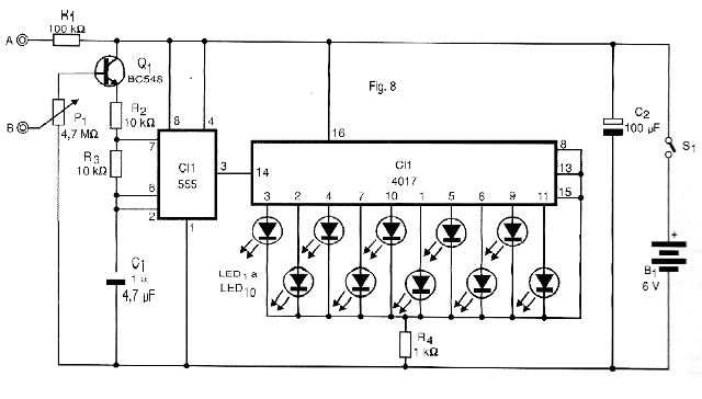
In Figure 8, we have the complete diagram of this biofeedback.
The arrangement of the components on a printed circuit board is shown in Figure 9.
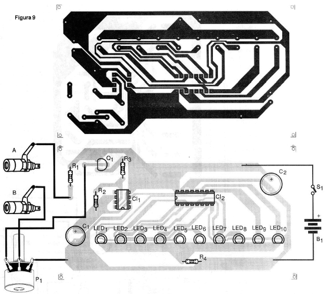
The power supply is made with 4 standard batteries and can be installed in a plastic box. The electrodes for operating with the pressure of the fingers can be the same suggested in the previous assembly with the difference that in this case we have only two metal plates.
USE
Rest your fingers on the electrodes and set P1 until the LEDs begin to run at a frequency that matches the desired rhythm, for example 4 to 7 times per second for the alpha rhythm.
If you do not achieve the desired frequency range, change the value of C1 to 220 nF or even 10 uF.
Then try to control the speed of the LEDs by the pressure and by observing them in a concentrated way until you get the complete relaxation.
For experiments with plants or other beings requiring greater input sensitivity use a potentiometer of 10 M ohms and eventually connect two transistors in the Darlington configuration.
Semiconductors:
CI-1 - 555 - integrated circuit
CI-2 - 4017 - integrated circuit
Q1 - BC548 - NPN general purpose transistor
LED1 to LED10 - Common LEDs of any color
Resistors: (1/8 W, 5%)
R1 - 100k ohm
R2, R3 - 10k ohm
R4 - 1k ohm
P1 - 4.7 M ohm - potentiometer
Capacitors:
C1 - 1 at 4.7 uF / 12V - electrolytic
C2 - 100uF / 12V - electrolytic
Miscellaneous:
S1 - Single switch
B1 - 6 V - 4 small batteries
Printed circuit board, mounting box, electrodes, wires, buttons for potentiometers, etc.
Circuit 3 - Digital Biofeedback - With PC interface
Our third design is presented in two versions: the first one drives a set of LEDs such that its ignition represents a digital value from 0 to 256, ie 8-digit binary, while the second applies binary values from 0 to 256 on the parallel port of the PC to control a feedback program.
The two circuits are based on the A/D (National Analogue-Digital ADC0804 converter) which features a good 8-bit output and operating speed (with 256 possible binary values).
The first circuit, driving LEDs, is shown in Figure 10.
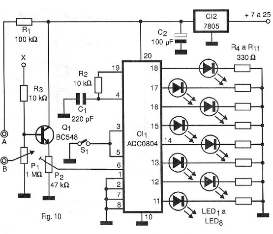
The binary value displayed by the LEDs will depend on the finger pressure on the electrodes connected between A and B. The sampling rate depends on C1 and R2 as long as the operating range is adjusted by both P1 and P2.
Switch S1 is to stop sampling if the reader wishes to have an indication of value at any given time.
The power supply can be made by an external source from 7 to 25 volts and, because the circuit needs a few milliamperes, the voltage regulator integrated circuit does not need a heat radiator.
The printed circuit board for this circuit is shown in Figure 11.
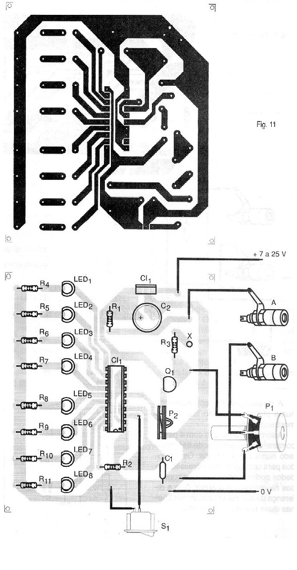
The assembly fits easily into a small box along with the source, and the electrodes are of the same type used in the previous designs. Point X can be used for triple electrode operation if desired.
For the second version, shown in Figure 12, we have the parallel port coupling made by an appropriate 25-pin connector.
In Figure 12, we have the diagram of this version of the device.
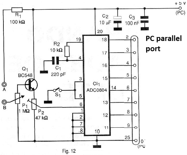
The 5-volt power can be removed from the computer itself as it will operate from it, and its consumption, being low, should not cause any overload to the source.
In Figure 13, we have the printed circuit board used in this design.
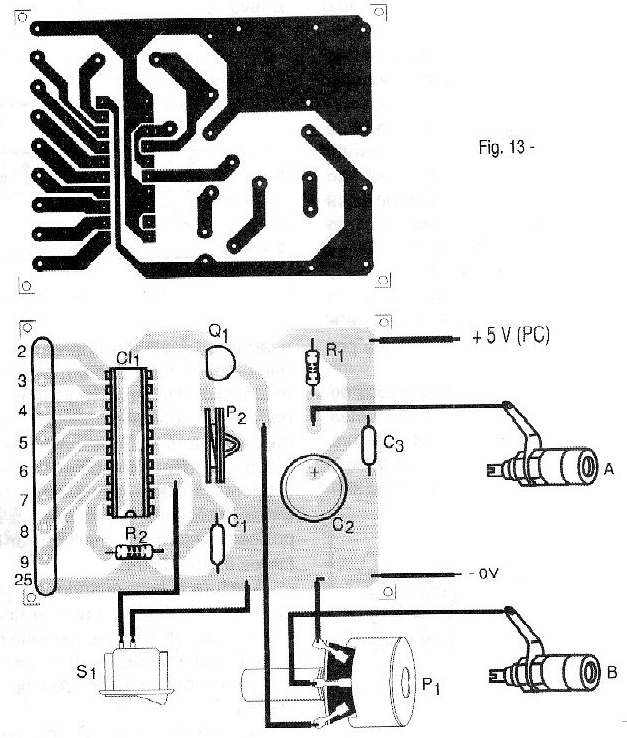
The program of data capture and processing can be done in Quickbasic, Visual Basic or even Delphi, depending only on the imagination of each reader to determine what it should produce in terms of acoustic or visual feedback.
a) design with LEDs
Semiconductors:
CI-1 - ADC0804 - Analog-digital converter - integrated circuit
CI-2 - 7805 - voltage regulator - integrated circuit
Q1 - BC548 or equivalent - NPN general purpose transistor
1 to 8 LEDs - Common red LEDs
Resistors: (1/8W, 5%)
R1 - 100k ohm
R2, R3 - 10k ohm
R4 to R11 - 330 ohm
P1 - 1 M ohm - potentiometer
P2 - 47 k ohm - potentiometer
Capacitors:
C1 - 220 pF - ceramic or styroflex
C2 - 100 uF / 6V – electrolytic
Miscellaneous:
S1 - Single switch
Printed circuit board, electrodes, mounting box, wires, welding, etc.
b) Interface PC design
Semiconductors:
CI-1 - ADC0804 - A/D converter - integrated circuit
Q1 - BC548 - NPN general purpose transistor
Resistors: (1 / 8W, 5%)
R1 - 100k ohm
R2 - 10 k ohm
P1 - 1 M ohm - potentiometer
P2 - 47 k ohm – potentiometer
Capacitors:
C1 - 220 pF - styroflex or ceramic
C2 - 10 uF / 12 V - electrolytic
C3 - 100 nF – ceramic
Miscellaneous:
Printed circuit board, mounting box, PC parallel port connector, electrodes, buttons for potentiometers, wires, welding, etc.


