
An electronic version of the pendulum can be used by the researcher, with the advantage that its oscillations can trigger a warning system and can even be used to detect a UFO at the exact moment it approaches.
The circuit we describe is extremely sensitive and should be an obligatory part of the field researcher's equipment.
In Figure 1, we show the apparatus being used in a field survey in order to detect eventual modifications of the gravitational field of the location in which a UFO descended.
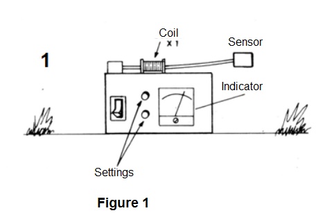
Left outdoors, it can also be used to check for changes in local gravity by the approaching a UFO.
How it works
In Figure 2, we have the complete diagram of the gravity sensor, using a high gain operational amplifier.
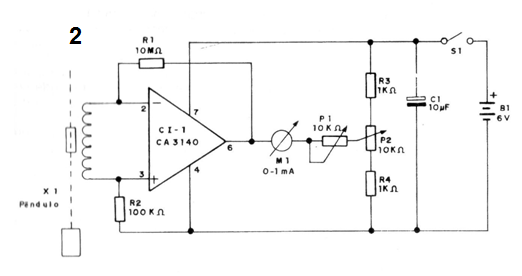
The sensor is a magnetic pendulum, ie, a pendulum that has a small magnet. Any oscillation of the pendulum causes the magnet to induce electrical signals which will be applied at the input of an amplified operational with very high gain.
The signals are amplified and applied to an indicating instrument in such a way that oscillations impossible to be visually perceived in the pendulum translate into strong movements of the indicator pointer.
The circuit is powered by 4 small batteries and its consumption is extremely low. This means that it can be permanently turned on without causing fast wear on the batteries, which should last for weeks.
The gain of the circuit is determined by R1. This component may eventually be replaced by a potentiometer of the same value, which will enable adjustment of the mode to prevent natural vibrations from the environment causing instabilities in the circuit.
The most critical part of this design is the assembly of the sensor, since it is a mechanical device. So, the care with which this sensor is built will depend on the sensitivity of the device. However, even the steps of a person several feet away can cause perceptible movement of the sensor pointer.
We also observed that this circuit detects variations of gravity or very small oscillations of the ground, also functioning as a sensitive seismograph.
Building the pendulum in an upright position, on the other hand, will allow oscillations in the horizontal direction to be detected.
An interesting possibility is to work with two sensors, one being built horizontally and the other vertically.
Assembly
The arrangement of the components on a printed circuit board is shown in Figure 3.
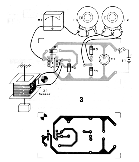
We suggest that the integrated circuit, given its sensitivity to static discharges, is placed in a socket.
The indicator instrument can be a typical milliammeter of 0 to 1 mA or any microammeter of greater sensitivity, like those used on amplifiers that work like VU-meters.
The resistors are 1/8 W or larger and the only capacitor is an electrolytic, for 6 V or more working voltage.
The two adjustment potentiometers are common.
Details of the construction of the sensor are shown in Figure 4.
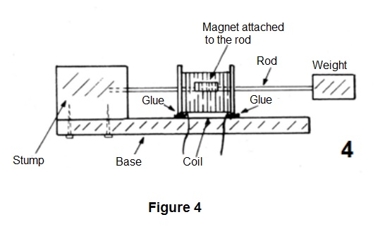
The coil is the primary winding of a common primary power transformer of 110 V or 220 V and any secondary. This transformer was disassembled and its core removed.
Built on a wooden base the reel of the winding is crossed by a rod in which there is a small permanent magnet trapped. This magnet can be obtained from keychains, refrigerator ornaments or any other type of object that has it.
The rod passing through the winding is made of metal, such as steel, and has a weight at one end, so as to facilitate its oscillations.
This way, any light vibration or action on the weight should cause the rod to oscillate and, consequently, the magnet, so that there is induction of signals in the sensor.
The assembly shown is so that the oscillations detected are mainly those which occur in the vertical direction. However, changes can be made in order to detect the oscillations in the vertical direction.
Test and Use
To test the instrument, turn on its power after inserting the batteries into the holder and set P2 so that the indicating instrument is with the needle at the center point of the scale. If this is not achieved, shield the sensor coil wires, as there may be buzzing from the power supply.
Then, lightly tapping the sensor, the needle should jump to the left or right, depending on the movement of the pendulum.
Set P1 so that the needle does not strike strongly at the end of the scale on a stronger sensor movement, which could damage the instrument.
Once the operation is confirmed, use the device only, leaving it to be monitored for vibration of the sensor. Remember that these vibrations imperceptible to us can indicate phenomena linked to the appearance of a UFO.
Semiconductors
Cl-1 - CA3140 or equivalent - operational amplifier with FET
Resistors (1/8 W, 5%)
R1 - 10 M ohms - (brown, black, blue)
R2 - 100 k ohms - (brown, black, yellow)
R3, R4 - 1k ohms - (brown, black, red)
P1 and P2 - 10 k ohms - potentiometers
Capacitor
C1 - 10 uF / 6 V - electrolytic
Miscellaneous
X1 - sensor - see text
S1 - single switch
M1 - milliammeter - see text
B1 - 6 V - 4 small batteries
Printed circuit board, battery holder, mounting box, buttons for potentiometers, wires, welding, sensor material, etc.


