We describe the assembly of a sensitive disturbance sensor of magnetic nature, that is, a field detector that can be used in paranormal investigations.
The circuit transforms into sounds, the signals created by alternating fields of low frequencies.
In addition to paranormal investigations, the device can be used in the detection of hazardous areas for health which can be generated by common devices and also responsible for interference and electrical noise.
The sensor is simply a homemade scout coil and power is drawn from ordinary batteries.
How it works
A coil with a ferrite core intercepts low-frequency fields, producing an electrical signal of the same frequency.
This signal is applied to a sensitive JFET operational amplifier which has a gain control, given by P1.
This amplifier increases the signal strength by up to 100.000 times, which gives the circuit huge sensitivity.
The amplified signal is applied to the input of an audio amplifier which has at its output a small speaker.
The circuit can be changed to use a low-impedance earphone at the output.
This way, intercepted signals are converted into audible sounds.
Assembly
In Figure 1, we have the complete diagram of the magnetic field detector.
13 Figure 1 - Ghostbusters diagram
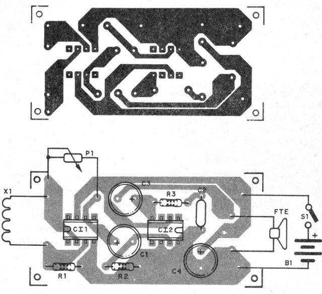
Its assembly can be done on a printed circuit board with the pattern shown in Figure 2.

In assembling, the positions of the integrated circuits and the polarities of the electrolytic capacitors must be carefully observed.
The resistors are 1/8 W with any tolerance and the electrolytic capacitors to 6 V or more.
The coil consists of at least 10.000 windings of very thin wire on a spool with a ferrite core.
One possibility is to take advantage of the primary winding of a small power transformer (110 V or 220 V) with any secondary voltage from which the core has been removed.
Another possibility is to take advantage of the coil of a residential buzzer.
We can also use a common telephone pickup coil.
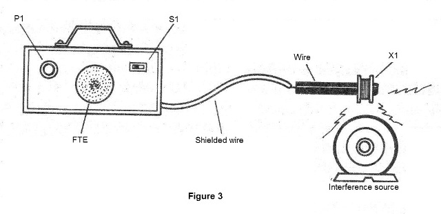
In Figure 3, we have a suggestion for the assembly with a shielded wire connecting the exploratory coil.

Turning on the appliance, approaching electric pipes and household devices, you will hear the power grunt on the speaker.
The gain is set at P1.
An interesting application for this device is as a telephone amplifier.
Approaching the coil of a telephone, we can hear the conversation on the loudspeaker.
The ideal position of the coil depends on the phone and must be obtained experimentally.
CI-1 - CA3140 - integrated circuit
CI-2 - LM386 - integrated circuit
S1 - Single switch
B1 - 6 V - 4 small batteries
L1 - Scroll coil - see text
P1 - 1 M ohm - potentiometer
R1 - 100 k ohm - resistor - brown, black, yellow
R2 - 10 k ohm - resistor - brown, black, orange
R3 - 10 ohm - resistor - brown, black, black
C1 - 10 uF - electrolytic capacitor
C2 - 47 nF - ceramic or polyester capacitor
C3 - 220 uF - electrolytic capacitor
C4 - 100 to 220 uF - electrolytic capacitor
FTE - 4 or 8 ohm - 5 to 10 cm speaker
Miscellaneous:
Printed circuit board, battery holder, mounting box, wires, welding, etc.


