

Obs. This project was originally published by a Brazilian magazine and them translated into English as part of my book Electronic Projects from the Next Dimension (Newnes 2001).
The sound can be produced by an amplifier that is fed from a variety of sources including microphones, to pick up the ambient sounds in biofeedback experiments, or a recording (CD or tape) with some relaxation sounds or special music.
Some experiments for this circuit are suggested below.
Experiments
The use of a stroboscopic light modulated by an audio source can help the subject in ESP experiments to be induced into trance state or to another appropriate mental state. The researcher can also verify how lamp flashes can interfere with the subject’s ability to apply paranormal skills.
In PK experiments, the experimenter can plug a microphone or other transducer into the input of the circuit and call on the subject to induce changes in the lamp’s flash rate using his mind. The circuit also can be used to produce special mental states during the experiments.
Some biofeedback and transcendental meditation experiments are also suggested. For instance, if we plug an oscillator that is controlled by skin resistance (as described in other articles in this section of the site) into the input of the circuit, the flash rate can be controlled by physiological changes in the subject’s body. Using a special audio source such as percussion sounds records or white noise, the flashes can be controlled to produce special states of mind, e. g., names or the fourth state of consciousness. The frequency can be adjusted to closely match alpha rhythms in many experiments.
For radiesthesia experiments, the researcher can compare the effect of a pendulum on a subject who is alternately exposed to the light of the stroboscopic source and not exposed to it. The source can help the subject achieve the trance state in experiments such as described before.
Experiments involving the EIP and EVP can be performed using this light source. The circuit also can be used to induce a trance or other state of mind insensitive subjects.
How It Works
The neon lamp, R1, P2, and C1 form a relaxation oscillator, driving the SCR.
The frequency can be adjusted within a wide range of values by P2. Depending on the experiment, capacitor C1 can assume values in the range of 0.1 to 1 µF. Large values will lower the frequency.
The pulsed dc power necessary to operate this stage comes from the ac power line passing through D1.
The modulation stage begins with a transformer whose function is to pick up the audio signals from any external audio source, and also isolate it from the circuit.
As common sources such as amplifiers have low-impedance, high-power outputs, the transformer must have a low-impedance winding as the input.
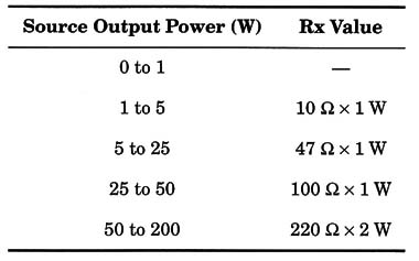
Resistor Rx is necessary to limit the power applied to the circuit, and its value is chosen according the amplifier or audio source power. The following table gives recommended values for this resistor.
According the output volume, P1 is adjusted to achieve the correct level of modulation. The signal is then applied to D2 and added to the pulses produced by the relaxation oscillator.
The SCR can control loads up to 3 A, but in this application we limited the loads to 100 W. See that the SCR is a half-wave control, and the lamp will flash with half of the total power. We can compensate for this by increasing the lamp power.
Assembly
Figure 1 is a schematic diagram of the psycholamp.

The circuit is mounted on a printed circuit board as shown by Fig. 2.

The transformer is the noncritical component of this construction. Any transformer with a low-impedance or low-voltage winding and a high-voltage or high-impedance winding can be used experimentally. In particular, power supply transformers with primary windings rated to 117 Vac or even 220/240 Vac, secondaries rated at 5 to 12 V, and current ratings in the range between 50 and 500 mA can be used.
The winding plugged into the input of the circuit (audio source) is the low-voltage one. The high-voltage winding is wired to P1.
The SCR is a TIC106, MCR106, or other equivalent in the “106” series. This component must have the suffix B or higher if the circuit is powered from the 117 Vac power line. If powered from the 220/240 Vac power line, the SCR must be rated for 400 V (Suffix D or higher).
The SCR must be mounted on a heatsink suited to the power of the controlled lamp. A piece of metal measuring 5 x 10 cm and bent to form a “U” is a suitable heatsink when working with loads up to 100 W.
The diodes also depend on the ac power line voltage. Use the 1N4004 for the 117 Vac power line or the 1N4007 for the 220/240 Vac power line.
In mounting the circuit, you must take care when installing it in a plastic or wooden box. The circuit is connected to the ac power line and can cause severe shocks if any live part is touched.
Although the circuit is powered from the ac power line, the audio source is isolated by the transformer and is no danger as long as its integrity is not compromised.
But the reader must be sure that the transformer used in this project is in perfect condition, with a high isolation resistance between windings.
The external lamp can be plugged into the circuit using a common plug and a piece of wire, according to the location in which the reader wants to install it.
Any common incandescent lamp with wattage ranging between 5 and 100 W can be used. The color is chosen according to the experiment.
The fuse is chosen according to the power of the controlled lamps. In an experiment, the reader can wire several lamps in parallel, since the total power does not exceed the limit of 3 A.
Testing and Using the Circuit
Connect the input of the device to the output of an audio amplifier shown in Fig. 3.
Plug the power cord to the ac power line and turn on the amplifier, with any program source (a tape recording, a microphone, etc.) as input.
Adjust the output volume to a comfortable level. It is not necessary to disconnect the loudspeaker from the output of the amplifier.
Set P1 to the minimum, and adjust P2 to obtain the desired lamp flash rate.
Then, go to P1 and adjust this control until you can see changes in the flashes that correspond to the variations in the sound level. At this point, the device is ready to be used. If a tape recorder is used as a sound source, you can plug it in from the monitor or phone output. In this case, resistor RX lS Eliminated.
Suggestions
Add a capacitor (C2) to change the frequency response of the device. If you include a high-value capacitor, the lamp will change in frequency only with the low-frequency sounds (bass).
Add a switch in series with D1. Opening this switch, the circuit is converted into a rhythmic lamp. The lamp will flash only with changes in the sound level applied to the input.
I You can use a black light (ultraviolet) such as found in night clubs (incandescent type) to perform experiments with invisible light.
Semiconductors
SCR - TIC 106B or TIC 106D silicon-controlled rectifier
D1, D2 - 1N4004 or 1N4007 silicon rectifier diode
Resistors
R1 - 27 k ohm, 1/8 W, 5% - red, violet, orange
R2 - 22 k ohm, 1/8 W, 5% - red, red, orange
R3 - 47 k ohm, 1/8 W, 5% - yellow, violet, orange
Rx - According the output power of the audio amplifier (see text)
Capacitors
C1 - 0.47 µF/ 100 V, ceramic or metal film
C2 - 0.01 to 0.47 µF, ceramic or metal film (see text)
Miscellaneous
T1- Any transformer with a high-voltage or high-impedance winding and a
low-impedance Winding (see text)
P1 - 47 k ohm potentiometer
P2 - 100 k ohm potentiometer
NE-1 - Any neon lamp (NE-2H or equivalent)
X1 - Outlet to the lamp
F1 - 5 A fuse
Printed circuit board, heatsink for the SCR, knobs for the potentiometers, plastic or wooden box, power cord, fuse holder, wires, solder, etc.


