

Thus, when we approach the explorer coil to any device which produces variable magnetic fields, we can “hear” these fields in the form of sounds, which facilitates their identification and even an eventual recording.
In fact, in a field research, you can connect the output of the mobile headphone to the input of a recorder to record the signals received. With this, the tape can be later analyzed with more time to determine the origin of the recorded signals.
An important point of this device is that it can be used to identify and differentiate fields of natural or man-made origin, such as those of power lines, from possible fields of unknown causes, possibly associated with the appearance of UFOs.
The device is powered by standard cell batteries and has excellent performance. The batteries have good durability, which means that a set of batteries can last for several days in a more intense research work.
In Figure 1, we show how the device can be used to detect possible fields, since it has directional characteristics.
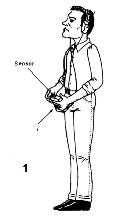
The lines of the field of unknown origin, when cutting the turns of the explorer coil, generate signals which turn into sounds on the headset.
If the readers want, they can use a small speaker instead of the earpiece, in which case the sounds reproduced can be heard by several people at the same time.
How it works
In Figure 2, we have the complete diagram of the magnetic field searcher.
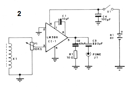
When the lines of force of the magnetic field to be explored cut the turns of the X1 coil, an electrical voltage or signal is induced which passes through a sensitivity control (P1) before entering an amplifier.
The amplifier is based on an LM386 integrated circuit which, in this configuration, has an amplification factor of 200 times, given by the C1 capacitor.
The amplified signal appears at pin 5 of the integrated circuit, being delivered to the output via CB. As the output is of low impedance, an 8 to 50-ohm headset must be used, the type found in walkmans or portable radios.
The C2 capacitor, together with R1, forms a network whose purpose is to keep the impedance low with high frequency signals, so as not to unstable the circuit.
The C4 capacitor decouples the power supply so that there are no instability problems.
The X1 sensor is the same as that of our first magnetic field detector consisting of a coil which must have the largest possible number of turns. A ferrite core inside helps to concentrate the lines of force of the magnetic fields, thus providing greater sensitivity.
The core used can be a ferrite rod of the type found in the internal antennas of medium wave radios. It will be easy to find an unused radio, from which this core can be removed.
*Assembly
The arrangement of components on a printed circuit board is shown in Figure 3.
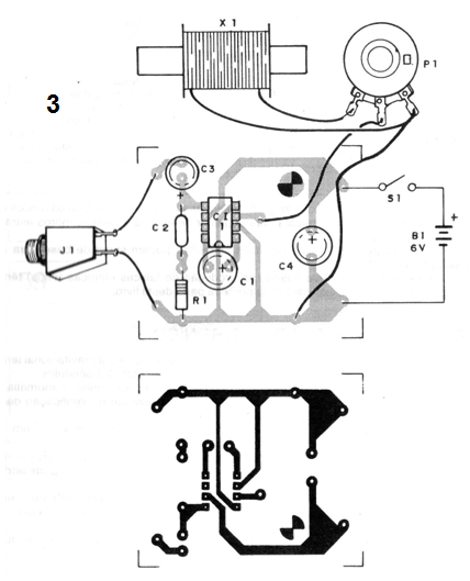
If the reader does not have much experience with assemblies that use integrated circuits, it will be interesting to use a socket for this component.
The resistors are all 1/8 W or greater and the electrolytic capacitors must have a minimum working voltage of 6 V.
The C2 capacitor can be either ceramic or polyester and the general switch can be incorporated into the sensitivity control, which is a common linear or log pot.
For the headphone, a jack compatible with the type you have must be used. For the sensor, if it is too far from the board input, a shielded cable must be used so that undesirable signals are not captured.
The whole set fits easily in a small plastic box. The size of this box must be designed so that the cell battery holder and the board are easily accommodated.
The explorer coil can be on the outside.
This coil can be the primary winding of a 110 V or 220 V power transformer and any secondary (which will not be used). The transformer is carefully disassembled, removing its core and replacing the ferrite rod. This rod, even though thinner than the original core, can be fixed with any glue.
Test and Use
To test the unit, just plug the headphone into the output, turn on the power and open the volume. Approaching the wire explorer coil to the electrical installation or any electrical or electronic device in operation, we should hear the roar of the power network in the headset.
To use the device, stay away from any device which produces snoring and pay attention to the signals you receive, which can range from crackling to strange beeps.
In field research, strange signals can work as a basis for the location of UFOs.
The crackles that you hear when producing electrical sparks (rays) have a natural origin, as explained in the first part of this book.
Semiconductors
Cl-1 - LM386 - integrated circuit, amplifier
Resistors (1/8 W, 5%)
R1 – 10-ohm - (brown, black, black)
P1 - 10k-ohm - potentiometer
Capacitors
C1 - 10 uF / 6 V - electrolytic
C2 - 47 nF - ceramic or polyester
C3 - 220 uF / 6 V - electrolytic
C4 - 100 uF / 6 V - electrolytic
Miscellaneous:
X1 - sensor - see text
J1 - headphone jack
S1 - simple switch - see text
B1 - 4 small or medium batteries
Printed circuit board, mounting box, cell battery holder, button for the potentiometer, material for the sensor, wires, solder, etc.


