Obs. The original text was produced to be part of my book Electronic Projects from the Next Dimension (2001), but the circuit can be used in other experiments.
The circuit is very small and highly portable. It is powered by common AA cells and has a very low current drain.
Several applications in experiments involving paranormal phenomena are suggested, starting with the use of the device as described below.
Experiments
The electrodes or sensors plugged into the input of this circuit are determined by the kind of experiment you want to perform. You can connect the circuit directly to the skin of a subject to detect any kind of electric signal generated by his body in ESP, PK, or transcendental meditation experiments. Two metal plates or rods can be used as electrodes.
We remember that the nervous cells of a subject produce voltage signals in the range of millivolts. It is these voltages that are detected by electrocardiographs and electroencephalographs. You can also plug a coil into the circuit to pick up magnetic fields, converting signals into sounds for ghost detection and other paranormal experiments.
Plug a coil (1,000 to 5,000 turns of 28 to 32 AWG wire in a ferrite core) into the input and try to use your mind or the mind of a subject to induce signals. The circuit can also be used to detect signals in the body of a subject during experiments involving PK.
In radiesthesia experiments, the influence of the pendulum on the body of a subject can be detected from the alterations in signals picked up with this amplifier. The experimenter can also plug a pickup coil into the input, as suggested for PK experiments, to see the influence of a pendulum.
In transcendental meditation and biofeedback, the subject can use signals from his own body and convert them into sounds to control internal physiological functions, as in other experiments involving temperature-to-sound or temperature-to-light converters.
In summary, whatever the reader wants to plug into the input of this device is a matter of choice. Phototransistors, pickup coils, microphones, and many other transducers and sensors can be used in these experiments.
The circuit can also be used as a remote-listening aid. By placing a microphone in another room (use a shielded cable), the experimenter can hear sounds produced by paranormal events. Use a high-impedance microphone to stimulate this amplifier.
Two metal rods or pieces of bare wire can be used to pick up sounds from the earth or water.
How It Works
The circuit has a very simple configuration based on a common bipolar transistor.
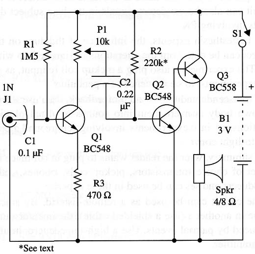
Three stages are used to amplify the low-frequency signal that is applied to the input. The first transistor is wired in a common collector stage, and the next two form a two-stage Darlington-coupled amplifier.
The very simple configuration has the advantage of being very easy to mount, even by beginners or persons less experienced with electronic mounting techniques.
Assembly
Figure 1 shows the diagram of the bioprobe.

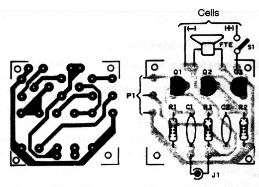
The circuit is mounted using a small printed circuit board as shown by Fig. 2.

Observe the position of polarized components such as the transistor. For the input, you can use a jack or, if you prefer, two pieces of wire with alligator clips on the end.
For the connection of the earphones or headphones, use appropriate jacks. The dimensions of the box are basically determined by the size of the printed circuit board and the cell holder.
Testing and Using the Circuit
Into the circuit input, plug a high-impedance microphone or a coil formed by 1,000 to 10,000 turns of any wire on a ferrite rod. Plug an earphone or a headphone into the output.
Turn on S1 and open P1 until you can hear something. In the case of the microphone, you’ll hear the ambient sound. In the case of the coil, you will pick up the “hum” of the ac power line or, in some cases, signals of some nearby radio stations (they will be mixed, as the circuit is not tuned).
If the sound is distorted when you open the volume control (P1), you must alter the values of R1 and R2. R1 can be varied in the range between 1.5 and 2.2 M Ω). In some cases, a resistor of even less than 1.5 MG must be used. R2 should be in the range between 220 and 470 k Ω).
When using the circuit, you only have to plug the sensor or transducer into the input of the circuit. If the signals are too low, it is because the transducer or sensor does not produce enough power to drive the circuit.
Suggestions
Replace Q3 with a TIP32 or BD136 and power the circuit from a 6 V or 9 V power supply to increase the output power. In this case, you can use a loudspeaker as the transducer.
Add a 0.01 to 0.047 µF capacitor in parallel with the input to reduce the high-frequency (treble) sounds.
Using the pickup coil, you can detect magnetic fields produced by the ac power line.
Semiconductors
Q1, Q2 - BC548 or equivalent-any general-purpose NPN silicon transistor
Q3 - BC558 or equivalent-any general-purpose PNP silicon transistor
Resistors
R1 - 1.5 to 2.2 M Ω, 1/8 W, 5% (see text)
R2 - 220 k Ω to 470 k Ω, 1/8 W, 5% (see text)
R3 - 470 Ω, 1/8 W, 5%-yellow, Violet, brown
Capacitors
C1 - 0.1 µF, ceramic or metal film
C2 - 0.22 µF, ceramic or metal film
Miscellaneous
P1 - 10 k Ω, potentiometer
S1 - SPST, toggle or slide switch (or ganged to P1)
B1 - 3 V, two AA cells
HP - Low-impedance earphone or headphone
J1 - Input jack or two alligator clips
Printed circuit board, battery holder, plastic box, knob for P1, wires, solder, etc.


