Capacitors can be obtained in a wide range of values and types which basically differ by the material used as dielectric which determines the basic characteristics of the capacitors, and hence where they can be used.
We then have the following types of capacitors most common found in electronics:
CERAMIC CAPACITORS
Ceramic is a dielectric material with excellent electrical properties to be employed in capacitors. However, because ceramic is not flexible, there are some limitations as to the values and shapes with which a capacitor can be made.
Ceramic capacitors can be found in three main forms: disk, tubular or plate which are shown in Figure 1.

Electrically there are not many differences between the three types, which means that the choice of another type for a project is basically conditioned to mechanical and value limitations.
Ceramic capacitors can be found in a range of values ranging from picofarad fraction to just over 470 nF, with insulation voltages from 25 V.
It is important to note that in most cases the marking of the insulation voltage is not done on the component, which requires the user to have the manufacturer's manual.
One of the main characteristics of ceramic, as a dielectric, is its ability to operate at very high frequencies, which makes this type of capacitor suitable for RF circuits.
Ceramic capacitors have their values represented by several types of codes with colored bands, numbers and letters and even with direct marking as shown in Figure 2.

PAPER AND PLASTIC CAPACITORS
Paper and plastic are dielectric materials with properties which make them suitable for the construction of capacitors.
Since plastic and paper are flexible, it is possible to build tubular capacitors according to Figure 3.

In fact, paper capacitors were the most used for a long time, at the beginning of the electronic age, and were later perfected by soaking the paper in oil.
This gave rise to the tubular oil capacitors, see Figure 4.

The main problem which occurs with these capacitors, however, is the absorption of moisture and the very loss of the properties of the oil over time. This causes these capacitors to "age" and cannot be used after a very long period of storage or even in an appliance.
Thus, every technician who wants to recover old appliances knows that one of the first tasks that must be performed is the exchange of all oil or paper capacitors for more modern types such as ceramic or plastic.
Currently, paper capacitors are hardly ever used, because plastic capacitors have better quality and price of the same order.
PLASTIC CAPACITORS
Several are the types of plastic that, because of their electrical properties, can be used in the manufacture of capacitors.
Depending on the type of plastic used, the capacitors receive specific designations with the following main types:
a) Polyester capacitors (metallized or not)
b) Polystyrene Capacitors
c) Polytetrafluoroethylene Capacitors
The main advantage of using polyester capacitors, instead of paper, is that in addition to plastic, they have a higher dielectric constant allowing smaller units to be built, their impermeability makes them much more reliable, with a much longer life.
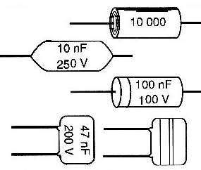
In Figure 5, we have some common types of plastic capacitors.
However, besides the advantages of plastic capacitors, we have to consider some disadvantages.
Polyester and polystyrene, for example, have high losses at high frequencies and are therefore not suitable for applications in circuits of high frequencies.
The maximum temperature they support is also not very high, and their use is not recommended above 70°C.
MICA CAPACITORS
Mica is a material with exceptional dielectric properties, which remains even at very high frequencies.
For this reason, these capacitors have been preferred in high frequency applications where high stability and reliability are required, eg, in instrumentation.
However, mica is a poorly flexible material with a dielectric constant not too high and its insulation is not the greatest, which means that the capacitors, besides having size and shape limitations, cannot be manufactured to withstand very high voltages.
Mica capacitors are manufactured in a range of values ranging from a few picofarads to 10 nF, with insulation voltages up to 250 Vrms.
In Figure 6, we have the traditional aspect of mica capacitors.

An important type of mica capacitor is the one which has the armor made by depositing a layer of silver. These capacitors, called "silver mica", are characterized by stability and high quality factor (Q factor) being used in instrumentation and even in radio transmission.

ELECTROLYTIC CAPACITORS
The electrolytic capacitors are formed by a plate in which a thin layer of their oxide is deposited by an electrochemical process, which becomes the dielectric, as shown in Figure 8.

Since this dielectric layer can be extremely thin, the capacitance obtained can be very high. However, this very small thickness does not tolerate high stresses.
Thus, we have the commitment of the voltage with the capacitance, which makes the electrolytic capacitors of the same voltage the greater, the greater the capacitance, and for the same capacitance the larger, the higher the working voltage, see Figure 9.

Common electrolytic capacitors are formed by an aluminum foil in which the oxide layer forms the other layer, forming the armature. Between each layer, there is a liquid substance called electrolyte which guarantees the electrical contact between both armatures.
We can get capacitors of very high values with this construction technique, however, there are several limitations as to their electrical properties.
The first, already seen, is the low operating voltage, which depends on the thickness of the dielectric oxide layer.
The second lies in the fact that the insulation layer is formed by a dielectric process involving the movement of a current in one direction. If a current in the reverse direction circulates through the component, it can destroy this dielectric. This means that electrolytic capacitors are polarized components.
The third limitation lies in the fact that the substance used as an electrolyte may lose its properties over time, and even evaporate, causing the component to lose capacitance, or even to short.
This is especially true if the component is out of use for a long time.
The fourth limitation is in the tubular construction of the component, which makes it very inductive and therefore not suitable for applications in high frequency circuits.
In Figure 10, we have some types of common electrolytic capacitors which can be found in a range from 0.47 ?F to more than 500 000 ?F.

TANTALUM CAPACITORS
The difference between ordinary electrolytes and tantalum capacitors lies only on the type of material used as dielectric, which has better electrical properties.
Since tantalum oxide has a much higher dielectric constant than aluminum oxide, a higher capacitance can be obtained in a smaller volume. This means that the tantalum capacitors can be much smaller than the electrolytic capacitors, as shown in Figure 11.

The tantalum capacitors are also polarized and can be found in values from 100 nF.
In addition to the smaller dimensions compared to ordinary aluminum electrolytes, tantalum capacitors also have a much higher temperature range and can even be used in temperatures below zero.
The main problem, however, for the use of this type of capacitor completely replacing the common electrolytic capacitors is the price, considering that tantalum is an expensive material.
CONCLUSION
In addition to the types indicated, there are other materials which can form the basis for the construction of capacitors. However, of the types found in common electrolytic equipment are in the above categories.
Knowing how to choose a capacitor for a particular application is very important to ensure its correct performance.