Enamelled wire as fuse
Never use a coin or aluminum foil (cigarette or household) in place of a blown fuse (*). If the circuit has a problem neither the coin nor the aluminum foil will stop the current at the right time. Thus, damage to the circuit is irreversible or to the electrical installation itself.
In the absence of a fuse of desired value the smart solution is to improvise a fuse with the same characteristics as the original. This can easily be achieved over a good current range by using enameled wires. What happens is that the thinner enameled wires have not very high maximum currents and if we know what these currents are we can use them to "recover" a fuse, as shown in figure 1.
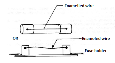
In table I we have the corresponding currents and wires to be used for the "recovery" of a fuse.
Table I
| Wire (AWG) | mm | Current (A) |
| 40 | 0.0031 | 1.77 |
| 38 | 0.0039 | 2.50 |
| 36 | 0.0050 | 3.62 |
| 34 | 0.0063 | 5.12 |
| 32 | 0.0079 | 7.19 |
| 30 | 0.0100 | 10.2 |
| 28 | 0.0126 | 14.4 |
| 26 | 0.0159 | 20.5 |
(*) In the past, when “blown” fuses were still used in domestic installations, when it was blown it was a common procedure to remove the blown fuse and put a coin in its place by tightening the old fuse thread. Pieces of aluminum foil were also placed. It was certainly a dangerous procedure, as the facility was no longer protected.
Demagnetizing tools
With use the tools can acquire some degree of magnetization which becomes unpleasant under certain conditions. Screwdrivers can "pull" screws when we put them in position, or even attract washers that were previously positioned.
Magnetism is acquired because the elemental metal magnets of the tool tend to align with its movement and attracted to metals always in the same way. There are two simple ways to break the magnetism of a tool.
a) The first is to subject it to heating above the Curie temperature, but this is not always possible because the tools may have plastic parts that would be affected.
b) The second is to subject the tool to an intense alternating magnetic field that misleads the elemental magnets. For this we initially have the circuit of Fig. 2 wherein the coil is the primary winding of a common (any secondary) power supply without core.
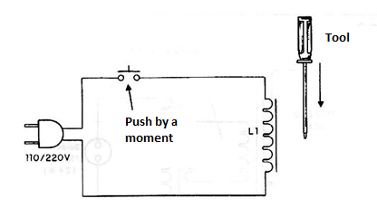
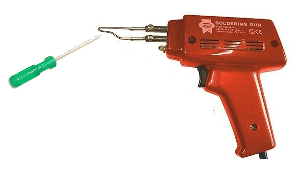
Pressing S1 for a moment and inserting the tool into the core of the primary will cause demagnetization (see that in the magnetization circuit a diode is used to obtain direct current). Another possibility is to use the welding gun. Simply place the magnetized tool as shown in figure 3 and squeeze the trigger.
Capacitive filter for DC motors
Small direct current motors can generate noise that is picked up by amplifiers, radios, recorders and other sensitive circuits. In addition, they can disable microcontrollers, shields and other digital control circuits. These engines mainly interfere with automotive appliances, especially the fan, windshield wiper motors and even the fan used in the engine cooling system.
Microcontrollers cause reset, instability and other problems. One way to reduce noise is to connect a 1000 uF x 25V electrolytic capacitor in parallel with the motor as shown in Figure 4.
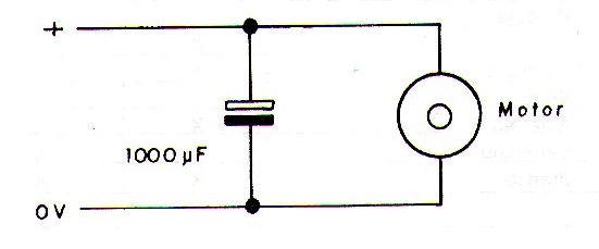
This capacitor will work as an excellent noise filter. Another possibility is to add the capacitor in parallel with the power supply of the interfering device, for example the car radio, a microcontroller or shield (see decoupling in this same book).
If, in this case, noise reduction does not occur, it is probably being picked up by the antenna system. The solution will be to prevent this noise from being radiated. In addition to the filter (capacitor) in parallel with the motor, its housing must be grounded. Poor grounding prevents it from working as a shield allowing noise to radiate.
Common silicon diodes as zeners
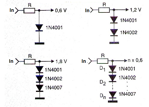
A common diode when forward biased produces a constant voltage drop between 0.6 and 0.7 V and can therefore be used as a zener for this voltage. In Figure 5 we show how we can use common diodes to simulate 0.6 V zeners (approximately) in various circuits.
We observe that the voltage obtained is not accurate and should be measured to give an accurate idea of its value, given the differences in characteristics of the diodes used, even though they are of the same type.
