

High voltage pulse generators may be useful in a variety of biological applications, for example in massages.
By adjusting the intensity and frequency control so as to obtain a patient's reaction, but without reaching the pain, one can stimulate the nerves and muscles in order to obtain a treatment.
Obviously, this should only happen under professional guidance, and this application is not therefore indicated to lay people.
For a more general use, however, we have biology experiments where we can stimulate plants, insects, etc., with safely produced electric pulses. The described device produces pulses of good intensity in a range from 0 to more than 500 volts and with frequencies which can be adjusted from a few tens a seconds to thousands a second. Depending on the application we can further reduce frequency by simply changing a component.
Features:
Supply voltage: 6 V to 12 V
Current: 1 A
Maximum output voltage: 500 V (approx.)
Maximum output current: some micro-amps (limited)
HOW IT WORKS
The circuit basically consists of an inverter based on a CMOS oscillator and a power field effect transistor.
We then have an oscillator around the IC, where the frequency is determined by as much as C1 and the feedback resistors R1, R2 and P1.
These components form a network which allows us to change only the separation between the pulses produced which have constant duration given by R1.
This is because C1 charges through P1 and R2 and discharges through R1. The diodes in inverted positions guarantee this behavior.
The signal produced by IC, a variable frequency pulse train, is applied to the other three IC ports which work as buffers and inverters.
The waveforms of the signal at the several points of the circuit are shown in Figure 1.
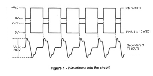
The output signal of the three final ports is applied through R3 to the hatch of a power field effect transistor.
This transistor is characterized by a resistance between the drain and the extremely low source when it is saturated, which guarantees an excellent transfer of energy to the low voltage winding of the transformer used as load.
The result is that the pulse applied to the low intensity transistor gate results in a high current pulse in the transformer secondary winding.
We have the induction of high voltage pulses in the primary winding of the corresponding transformer.
As the waveform of these pulses is not sinusoidal, for which the transformer is dimensioned, we also do not have the expected voltage production. In fact, because of this faster switching, a transformer with primary winding of 220 V, for example, can present, in this circuit, peaks of more than 500 V.
This high voltage works either for the output or for lighting a neon lamp.
The potentiometer P2 determines the voltage to be applied to the external element. The electrodes connected to the stimulated element depend on the application.
For a "prank" that checks the sensitivity of a person, this electrode can be made, for example, with two spent batteries with the external scraped paint, which must be held by one’s hands.
ASSEMBLY
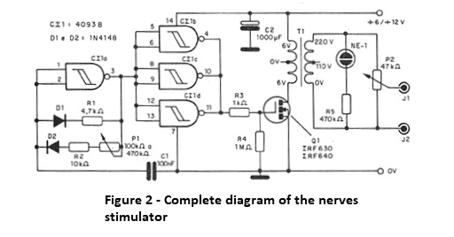
In Figure 2, we have the complete diagram of the apparatus.
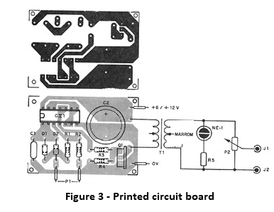
We have the arrangement of the components on a printed circuit board. The power can be supplied with ordinary large batteries (4) or power supply, shown in Figure 3.
In case the power is supplied by batteries, the autonomy of the appliance will not be greater, given the high current demanded.
The integrated circuit must be placed in a DIL socket and a small heat radiator, a rectangular or U-folded metal plate must be attached to the power transistor.
The transformer T1 is of the type used in sources, with a primary of 220 V and a secondary of 6 V + 6 V and current from 500 mA to 1 A.
Other secondary voltages also allow its work, and even types of winding without derivation (single windings).
The resistors are 1/8 W with 5% or more tolerance and the electrolytic capacitors must have working voltages of 16 V or more.
The neon lamp is the common one for parallel terminals, and the potentiometers can be log as well as linear.
PROOF AND USE
When the unit is powered on, the neon light should light.
Connecting a multimeter to the output (between J1 and J2) will not indicate the correct voltage due to the signal waveform as well as the low resistance of common devices.
To really test for high voltage, put P2 in the least resistance position and hold a pair of peeled wires connected to J1 and J2, as shown in Figure 4, between your fingers.
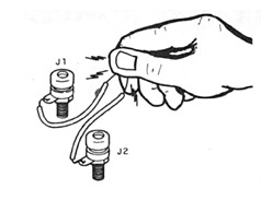
Then gradually open P2 until you feel a tingling between your fingers, which characterizes the presence of high tension.
Also act on P1 to see how this tingling sensation changes.
After proven the operation, definitely install the device in a box and use it sparingly and preferably on non-humans and always with expert guidance.


