(*) See in books of the author about Robotics , Mechatronics and Artificial Intelligence and Mechatronics Sourcebook.
When an SMA is cold (i.e., below its transformation temperature), it has a very low yield strength and can be deformed quite easily. Below the transition temperature, it has a tendency to retain the deformed shape. In most cases, the transition temperature of the SMA is chosen such that the transformation point of the material is well above room temperature.
If the material is heated to its transformation temperature, it undergoes a change in crystalline structure. This change causes it to return to its original shape.
If the SMA encounters resistance during this transformation, it can generate extremely large forces, providing a unique mechanism for remote actuation.
The most common shape memory material is an alloy of nickel and titanium called nitinol. This alloy has very good electrical and mechanical properties, long fatigue life, and high corrosion resistance.
As an actuator, it is capable of up to 5 percent strain recovery and 50,000 psi restoration stress over many cycles.
Nitinol also has resistance properties that enable it to be actuated electrically by j oule heating. When an electric current is applied to nitinol, it can generate enough heat to cause the phase transformation.
PHYSICAL PROPERTIES OF NITINOL
Nitinol is available in the form of wire, rod and bar stock, and thin film. Its physical properties are as listed below.
Density: 6.45 g/cc
Melting temperature: 1240-1310°C
Resistivity (high-temperature state): 82 u ohm-cm
Resistivity (low-temperature state): 76 u Ω-cm
Thermal conductivity: 0.1 W/cm-OC
Heat capacity: 0.077 cal/g-OC
Latent heat: 5.78 cal/g; 24.2 J/g
Magnetic susceptibility (high-temperature): 3.8 uemu/g*
Magnetic susceptibility (low-temperature): 2.5 uemu/g
MECHANICAL PROPERTIES OF NITINOL
Ultimate tensile strength: 754-960 MPa or 110~14O ksi
Typical elongation to fracture: 15.5 percent
Typical yield strength (high-temperature): 560 MPa, 80 ksi
Typical yield strength (low-temperature): 100 MPa, 15 ksi
Approximate elastic modulus (high-temperature): 75 GPa, 11 Mpsi
Approximate elastic modulus (low-temperature): 28 GPa, 4 Mpsi
Approximate Poisson’s ratio: 0.3
ACTUATION CHARACTERISTICS
Energy conversion efficiency: 5%
Work output: ~1 joule/ gram
Available transformation temperatures: -100 to +100°C
COMMON SMA CHARACTERISTICS
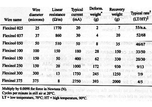
In Table 1, we display some important characteristics of SMAs (information derived from the Robot Store catalog).
HYSTERESIS
When the wire heats under a constant force, its contraction follows the right-hand curve shown in Fig.1. When the temperature reaches the point As, the wire has started to shorten. Nearly complete contraction is achieved when the temperature reaches Af.
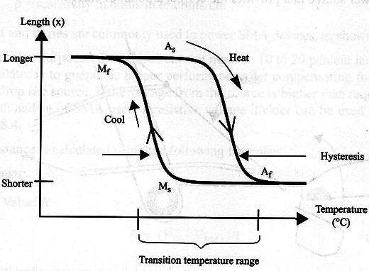
As the wire cools, the left-hand curve is now followed, starting at lower right and passing through Ms and Mf. MS is the point where the wire begins to relax again, and Mf is the point where the wire is almost fully relaxed.
USING SHAPE MEMORY ALLOYS
Shape memory alloys can be used wherever a short pull or push is needed.
One of the most popular applications for SMAs is in robot muscles and in bionics in arttificial muscles.
In the following text, we look at some important considerations in the use of SMAs, with the aim of determining whether an SMA is the best choice for a particular project.
MECHANICAL CONSIDERATIONS
Figure 2 gives an example of a typical SMA application in which a wire works as an electric muscle to drive a robot arm.The same principle can be applied to bionic muscles in artificial hands, arms and legs.
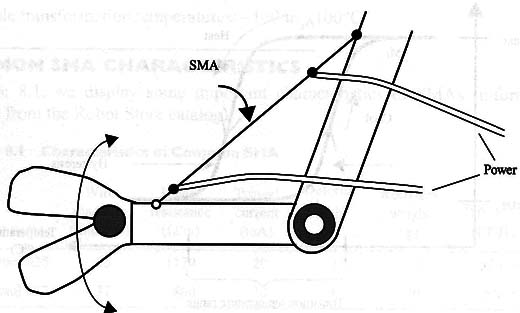
When the SMA is driven by a current source, it acts on the arm to release force. The amount of force generated at the end of the arm can be calculated from the SMA force and the characteristics of the arm.
It is important to choose the proper wire gauge for your application. If the force generated at the end of the arm exceeds the maximum capacity of the wire, the wire will break.
Another characteristic to be considered is mechanical fatigue. An SMA can contract and release a limited number of times, so life expectancy is an important factor.
ELECTRICAL CONSIDERATIONS
The circuit that you will need to drive the SMA is another consideration in any project. Excess current can break the SMA, and insufficient current will not generate enough heat to bring the wire to its transition temperature; hence, it will no contract as required.
You therefore need to consult the manufacturer’s specifications and use a power source that provides the correct amount of current.
Below, we consider two types of power sources: a simple voltage source and a constant-current source.
Simple Voltage Source
In simple cases, if we know the voltage of the power source and the specific resistance of the SMA (in Q/m or Q/cm), we can use a simple calculation to determine the length of wire necessary for a particular operating current.
First, we use Ohm’s law to compute the total resistance that the wire must have to produce a flow that matches the SMA’s nominal current rating so as to achieve the desired change in shape.
Formulas:
R = V/I (1)
where
R = resistance in Ω
V= voltage of the power source in volts
I = current required by the SMA in amperes
In the second step, we calculate the length of SMA that produces the required resistance.
L = R/? (2)
where
L = final length in meters or centimeters
R = total resistance in Ω
?p = resistivity in Ω/m or Ω/cm
Cells and batteries are commonly used to power SMA devices, as shown in Fig. 3.
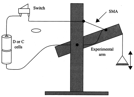
For practical purposes, the applied current must be 10 to 20 percent larger than the calculated one to guarantee proper performance after compensating for some voltage drop in the source.
If the voltage from the source is higher than required for the length and type of SMA used, a resistive voltage divider can be used as shown in Fig.4.
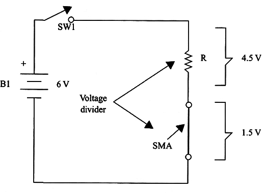
Resistance R is calculated using the following formulas:
Formulas:
a. Value of R
R = (Vin- VSMA)/I (3)
where
R = added resistance in Ω
Vin = input voltage in Ω
VSMA = voltage required to drive the SMA in the application
I = current passing through the SMA in amperes
b. The dissipation of R is given by
P = R x I2
where
P = power dissipated in watts
R = resistance of the added resistor in Ω
I = circuit current in amperes
Obs.: Use a wire-wound resistor with at least twice the calculated value to avoid exceeding the device’s dissipation limit.
* In critical applications, we must also consider that the resistance of the SMA changes as it is heated resistance increases with heat, so the current flow drops.
Constant-Current Source
Although a simple current source is applicable, optimal SMA performance is obtained through the use of a constant current source. This kind circuit of circuit maintains a constant circuit current independently of the Circuit’s resistance and the input voltage, and it can do so within a wide range of both voltage and resistance.
Figure 5 shows a simple constant-current source. It uses an adjustable voltage regulator IC such as the LM150/LM317/LM350T or any equivalent.
The LM350T, for instance, can provide a load with currents up to 3 A.
The value of R depends on the desired current in the load. It can be calculated using Eq. (5).
Formula:
R = 1.25/1 (5)
where
R = circuit resistance in Ω
I = required current to drive the SMA in amperes
In Eq. (5), the 1.25 value is the internal reference voltage of ICs such as the LM150, LM350, and LM317. If another type of IC is used, the specification sheet will give the internal voltage reference to be substituted for the 1.25 value.
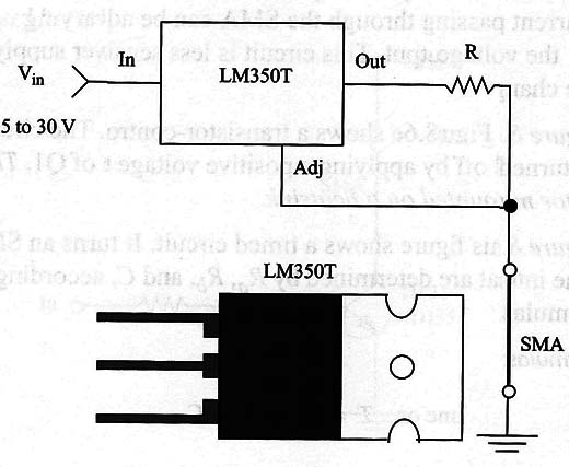
The value of Vin is derived from the resistance of the SMA or the voltage necessary to drive it. If we know the SMA resistance and the current passing through it, we can calculate the voltage required to drive it using Ohm’s law.
Formula:
V = RSMA x I (6)
Where
V= voltage across the SMA in volts
RSMA = resistance of the SMA in Ω
I = current in amperes
Vin must be at least 2 or 3 V higher than VSMA.


