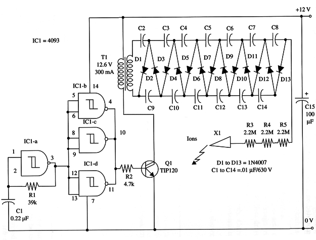
The circuit we present here generates negative ions and can be used in experiments to determine their effects. As the ion level varies according the used components, we do not recommend that the reader use this project at a home or business until making a precise measurement of the amount of ions generated by it.
The circuit is basically a high-voltage generator that produces, via an electrode, a constant flux of negative ions. These ions are dispersed into the ambient air, affecting living beings in the vicinity.
In the circuit, IC1-a acts as a low-frequency oscillator that drives a buffer (IC1-b, c, and d) and a power output transistor. The transistor has as its load a small transformer that generates a high ac voltage of about 150 V.
This high voltage is applied to a voltage multiplier that produces an output about of 2 kV. This voltage is enough to produce a constant flux of ions through the electrode X1.
The circuit is powered from a 12 V source as an ac-to-dc converter or a battery. Current drain depends on the components and typically is between 100 and 500 mA.
A schematic diagram of the Negative Ion Generator is shown in Fig.1.

IC1 - 4093 CMOS integrated circuit
Q1 - TIP120 NPN Darlington power transistor
D1 - D13 - 1N4007 (1 A, 800 V) silicon rectifier diodes
T1 - 12.6 V, 300 mA transformer, Radio Shack 273-1385 or equivalent, primary 117 Vac
X1 - Electrode (see text)
R1 - 39,000 Ω, 1/4 W, 5% resistor
R2 - 4,700 Ω, 1/4 W, 5% resistor
R3, R4, R5 2,200,000 9, 1/4 W, 5% resistors
C1 - 0.22 µF ceramic or metal film capacitor
C2 - C14 - 0.01 µF, 630 WVDC ceramic or metal film capacitors
C15 - 100 µF,16 WVDC electrolytic capacitor


