Obs.: the original article was written in Portuguese and translated into English to be part of my book Bionics for the Evil Genius.
The aim of a biofeedback device is to use electronics to form a loop involving a living being and an electronic circuit in a manner that one can interact with the other, as shown in Figure 1.
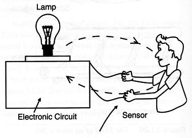
So, by controlling one’s emotions or reactions, the living being can actuate the electronic circuit, which controls external devices or gives a response that can be observed by the researchers.
For this device, the term visual comes from the fact that the indications of the control of the specimen on the circuit comes in a visual form. A lightemitting diode (LED) pulse frequency depends on the current flowing across the loop formed by the living being and the electronic circuit.
We also suggest that the reader take a brief look at the “Ideas to Explore” section suggested there.
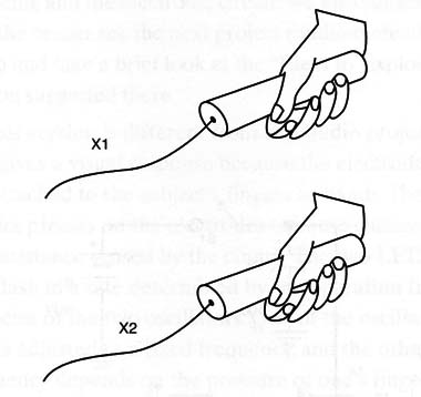
This version is different from an audio project (as the one published in this section), as it gives a visual response because the electrodes are attached to the subject’s fingers or hands. The subject presses on the electrodes to cause changes in the resistance sensed by the circuit.
The two LEDs will flash in a rate determined by the operation frequencies of the two oscillators. One of the oscillators is adjusted to a fixed frequency, and the other’s frequency depends on the pressure of one’s fingers on the electrodes.
The subject should control the pressure of his or her fingers or hands on the electrodes in Oder to have a constant light pulse rate produced by the LEDs. The electrodes can also be placed on other parts such as the face, head, arms, or legs, according to the experiment the reader wants to conduct.
Many experiments can be performed using this circuit:
Test your capacity to control the circuit using your mind. For example, changes in the mind can cause changes in the electric resistance of the skin in many parts of the body. This, in fact, is the operating principle of the electroencefalograph.
Test the changes in the subject’s ability to control the LED when the subject is under stress.
Make collective experiments with many persons controlling the same circuit at the same time.
Test if a living being can alter the flash rate under conditions determined in an experiment.
How it Works
Most of the biofeedback circuits use changes in skin resistance to alter their operational characteristics.
The changes can alter the frequency of a signal, change the intensity of a lamp, or trigger some kind of alarm. This circuit uses the skin resistance to control the frequency of a low-frequency oscillator driving the LEDs.
When the resistance is low, the time constant of the circuit is reduced and its frequency increases by the same amount. This means that small changes in the resistance will be translated into small changes of the LEDs’ flash rate.
To show this, we use a 4093 complementary metal oxide semiconductor (CMOS) integrated circuit (IC) formed by four NAND Schmitt triggers as the start point. Two of its gates are used as oscillators, and the other two are used as digital buffers driving two LEDs. One oscillator produces signals in a frequency given by C1 and adjusted by P1.
The other oscillator generates a signal with a frequency determined by C2 and the resistance between the electrodes.
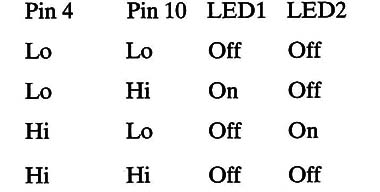
Observe that one LED lights up when the output of the buffer ICl-b (pins 5,6, and 7) goes high and IC2-c (pins 8, 9, and 10) goes low, and the other LED lights up at the inverse condition. The following table outlines these conditions:
| Pin 4 | Pin 10 | LED1 | LED2 |
| Lo | Lo | Off | Off |
| Lo | Hi | On | Off |
| Hi | Lo | Off | On |
| Hi | Hi | Off | Off |
Figure 2 shows the schematic diagram of the visual biofeedback.
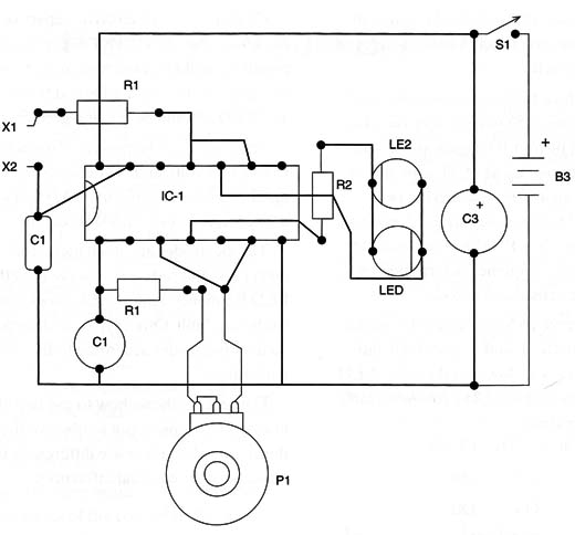
The circuit is mounted on a printed circuit board (PCB), as shown in Figure 3.
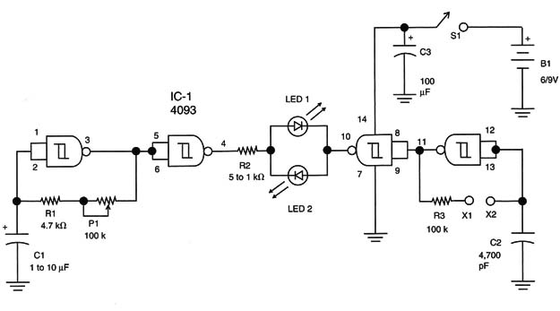
C1 and C3 are electrolytic capacitors rated to 12 working voltage DC (WVDC) or more, and their position should be observed, as they are polarized components, like the LEDs and the power supply.
The LEDs should be red and green. The circuit can be powered from supplies ranging from 6 to 9 volts, and R2 depends on the supply voltage. For a 6-volt supply, use a 1,000 Ω resistor and for a 9-volt supply use a 1,500 Ω. resistor.
The electrodes are small metal rods. The subject must press the rods and observe the effect on the LED frequency. Figure 4 shows how the electrodes are built.
Other types of electrodes can be created by the reader according to the experiments to be performed.
Figure 5 shows how to use two electrodes inserted into a plant pot to observe the frequency of the circuit when there are differences in light, stress, noise, or other external influences.
Testing and Using
Turn the power on using SI and adjust P1 to a flash rate of about one or two flashes per second (1 or 2 Hz). This adjustment should be made with the elec-trodes in your hands but without one touching the other. After this, try to control the electrodes flash rate, one in each hand, by changing the pressure on them.
Additional Circuits and Ideas
A flashing lamp can be controlled from the skin resistance monitored by sensors in many different ways. Besides the one described in the basic version, others are given here, using different techniques and components.
IC1- 4093 CMOS integrated
LED1 - LED: Common red
R1 - 4.7 k Ω, 1/4-watt, 5%
R2 - 1 k Ω, 1/4-watt, 5%
R3 - 100 k Ω, 1/4-watt, 5%
P1- 100,000 Ω potentiometer
C1- 1 to 10 µF/12 Vwvdc electrolytic capacitor
C2 - 4,700 µF to 0.47 µF ceramic or metal film capacitor
C3 - 100 µF/12Z WVDC electrolytic capacitor
S1: Single pole, single throw (SPST) toggle or slide switch
B1: Four 6 to 9 V AA cells or battery
X1, X2: Electrodes (see text)
Other: PCB, cell holder, plastic box, wires, solder, etc.


