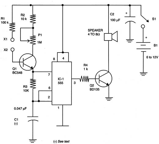
Figure 1 shows an audio feedback setup that can drive a small loudspeaker, which is much more powerful than the piezoelectric transducer used in the basic version.

This circuit is formed by only one oscillator, so the subject (the person or animal) must control the tone generated by the circuit, not cancel it. This circuit uses a 555 TC configured as an astable multivibrator. The frequency is controlled by the resistance between the positive rail of the power supply and pin 7.
P1 adjusts the basic frequency, and Q1 is used as a variable resistor that changes the resistance according to the amount of base current. Because the base current depends on the resistance between the electrodes (X1 and X2) and it is given by the skin of the subject, it is clear that the frequency reproduced by the loudspeaker depends on the amount of feedback of the person connected between the electrodes.
The circuit is very sensitive due to the presence of the transistor, and even resistances of many megΩ will cause the circuit to produce audible sounds or clicks. Of course, not just people can be connected to the electrodes. Animals, plants, and even aquariums can be used.
To control the sensitivity, a 4.7 M Ω potentiometer can be wired between the base of Q1 and the 0-volt rail of the circuit.
C1 determines the center frequency of the oscillator and can be changed according to the application.
The reader is free to experiment using values between 0.470 and 100 µF.
The circuit can be powered from cells or a power supply with voltages between 6 and 12 volts. When using power supplies above 9 volts, the transistor Q2 must be mounted on a heatsink. If a power supply is used, it must have a transformer.
Do not use transformerless power supplies because they are not isolated from the AC power line, and the electrodes could cause severe shock hazards.
The circuit can be mounted using a printed circuit board (PCB) or a solderless board. The electrodes are the same as in the basic project, depending on the application.
A Darlington power transistor, such as the TIP120, can be used, replacing Q2. It is capable of handling a high-power loudspeaker. For that reason, it is necessary to increase R4 to 4.7 k Ω.
Testing and Using
The first step in testing is to power on the circuit. If the electrodes are separated, the loudspeaker will not produce any sound. Maybe some random clicks will be heard due to any current loss in the transistor.
If you place your fingers on the two electrodes at the same time, the loudspeaker will produce a tone, acting on P1. You will see that the tone will change when you apply pressure to the electrodes.
IC1 - 555 integrated circuit
Q1- BC548 or equivalent - NPN general-purpose silicon transistor
Q2 - BD135 or equivalent NPN medium-power silicon transistor
X1, X2 - Electrodes
SPKR - 4 to 8 Ω- 5 to 15 cm loudspeaker
R1- 100 kΩ x 1/8 W resistor, brown, black, yellow
R2, R3 - 10 kΩ x 1/8 W resistor, brown, black, orange
R4 - 1 kΩ x 1/8 W resistor, brown, black, red
P1 - 1 MΩ potentiometer, lin or log
C1- 0.047 µF ceramic or polyester capacitor (see text)


