See BM021 and BM022 for more details about the use of magnetic fields in bionic experiments.

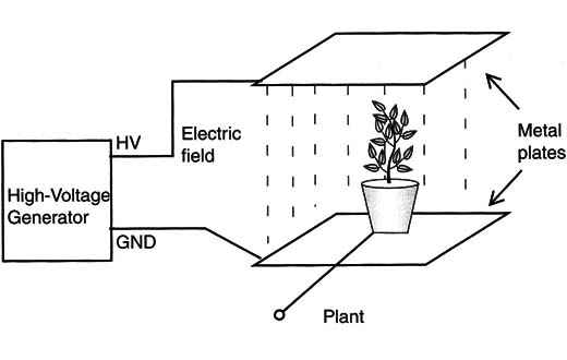
The strong electric field applied to the specimen can cause changes in its behavior. The reader can perform experiments to see how some fruit or a plant’s flower is altered under the influence of this field, such as if it grows faster.
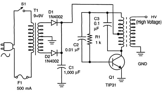
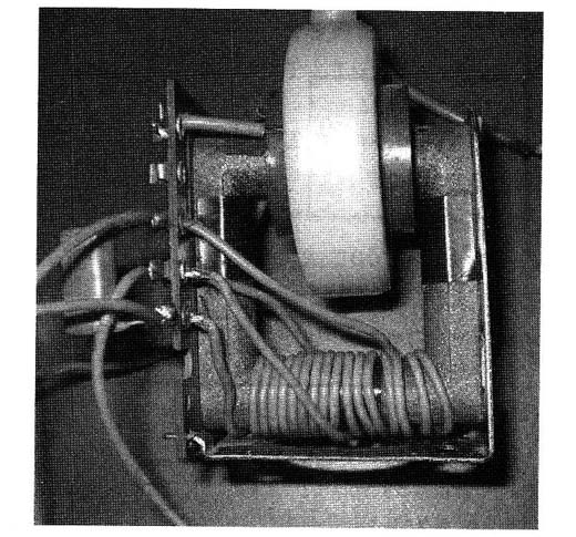
The circuit consists of a Hartley oscillator, having a high-voltage transformer as its load. This high-voltage transformer is a fly-back one, like the ones used to generate a high voltage in computer video monitors and television sets. Figure 2 shows this component and how the coil is wound in its core.

The high voltage in the secondary of the coil can be used directly if the reader wants to perform experiments with alternating electric fields, as shown in Figure 3.

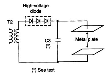
But if the reader wants to apply static (continuous) fields to the plant, the rectifier and filter shown in Figure 4, diodes must be added.

The electrodes consist of two metallic plates measuring from 10 X 10 cm to 50 X 50 cm. The reader must be careful to not touch these plates when the circuit is in operation due to the high voltage, which could cause a severe but nonfatal shock.
The homemade capacitor C3 consists of two metal plates, with a glass plate between them as a dielectric that is 0.3 to 0.5 cm thick. The circuit can also be used to perform electrostatics experiments in a physics lab.
Q1: TIP31 silicon NPN power transistor
D1, D2: 1N4002 silicon rectifier diodes
C1: 1,000 µF x 25 V electrolytic capacitor
C2: 0.01 µF ceramic or polyester capacitor
C3: 0.1 µF ceramic or polyester capacitor
R1: 1 k ohm x 1/2 W resistor, brown, black, red
T1: Transformer, with the primary according to the AC power line and the secondary at 9 + 9 V or 12 + 12 V x 500 mA
T2: Fly-back transformer (see text)
S1: On/off switch
F1: 500 mA fuse and holder
For the high-voltage rectifier:
D3: High-voltage rectifier at 10 kV or higher
C4: Homemade capacitor
Other: Power cord, plastic box, solder, wires, etc.


