Note: this article was originally published in Brazil, and them translated and adapted to be Evil Genius (TAB – 2006).
According to the Handy Science Reference Book (Carnegie Library of Pittsburgh, 1994), “A negative ion generator is an electrostatic air cleaner that sprays a continuous fountain of negatively charged ions into the air. Some researchers claim that these ions cause a feeling of well being, increased stamina and relief from headaches, allergies and asthma.”
It is not difficult to build an ion generator for experimental purposes and even make experiments with living beings. The reader can make experiments to see how the presence of ions in an area can affect plant growth or the behavior of insects or other small creatures.
Our basic project is a simple ion generator that, although powered from the AC power line, is very safe and can be used for medicinal purposes. The circuit will produce negative ions, but with a simple inversion of the diodes it can be changed to produce positive ones. The use of the device requires professional observation (a medical doctor, for instance, because it is for medical purposes).
The production of negative and positive ions is done by very high-voltage sources that range from 1,500 to 30,000 volts, but the current drain is very low, which does not represent the additional demand on your energy bill at the end of the month. The power demand of the circuit is low, less than 2 watts.
Bionic Application of the Circuit
Producing negative (or positive) ions in an area is not a proper interaction between a living organism and an electronic circuit. The purpose of the project is to create conditions in order to investigate how electric charges can alter the behavior of living beings. The experiments can be made With:
Plants
Insects
Microorganisms
The device can also be used to investigate how ions can affect people with allergic diseases. In this case, with the supervision of a doctor, the device can be used at home or in the car.
How It Works
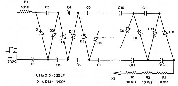
The circuit is a voltage multiplier with 13 stages, which increase the peak of the AC power line voltage up to 1,800 volts. This voltage is enough to generate a constant flux of ions in the electrode. Of course, the reader is free to increase the number of stages, producing higher voltages.
When the circuit is powered on, each capacitor charges with the peak voltage of the AC power line, something near 150 volts. If the circuit is powered from the 220/240 VAC power line, the output voltage doubles. In this case, it is possible to use fewer stages to generate enough voltage for a good flux of ions.
Since the capacitors are wired in a series, between semicycles, they are discharged through the output, appearing as the sum of their voltages in the electrode.
The resistors are important for limiting the current in case of accidental contact with the electrodes, because the circuit is powered directly from the AC power line.
The capacitors are not critical in this circuit. Values between 0.1 and 0.47 µF can be used, and they determine the amount of ions generated by the circuit.
The electrode is a needle or another metallic object with a sharp point. The reader can add a fan, such as one found in a computer, to spread the ions in the area.
Building the Ionizer
Figure 1 shows the complete schematic diagram of the basic version.

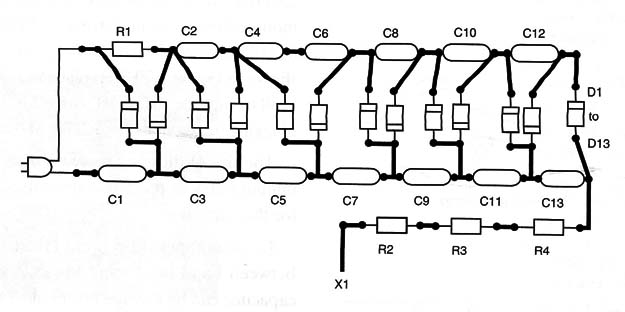
The circuit can be mounted on a small printed circuit board (PCB), as shown in Figure 2.

As explained before, the number of stages can be altered if the reader wants higher or lower voltages for the application in mind.
Testing and Using
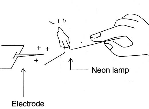
First, plug the circuit to the AC power line. Then place a small neon lamp near the electrode and, from the influence of the high-voltage field, it should glow, as shown in Figure 3.

At the same time the ozone gas is produced, the presence of the ions will also be indicated by a characteristic smell being emitted.
D1 to D13: 1N4007 silicon rectifier diodes
Cl to C13: 0.22 µF x 400 V polyester capacitors
R1: 100 ohm,x 1 W resistor
R2, R3, R4: 10 M ohm,x 1/8 W resistors, brown, black, blue
X1: Electrode (see text)
Other: PCB, power cord, wires, plastic box, solder, etc.


