A first version of this article is given in BM013E. The article was originally included in my book Bionics for the Evil Genius and first published in a Brazilian magazine.
The project described here is a device that converts ultrasounds into sounds, allowing the reader to have a “bat ear.” Many sounds in one’s environment that cannot be heard by humans will be revealed with this device. The circuit is only experimental, so it is open to many improvements.
The circuit divides the frequency of the ultra-sounds but does not maintain their original wave-shape. This means that what the evil genius will hear is not exactly the original sound, but something near it.
The sensitivity of the device depends on the transducer used to pick up the sounds. For experimental purposes, even a piezoelectric tweeter can be used for this task, reaching frequencies of up to 25,000 Hz.
The circuit is powered from common cells, which would allow portable use.
The evil genius can use it to explore nature, as suggested by Figure 1.
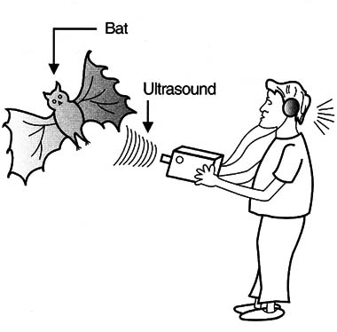
The sounds of bats and other animals can be heard using this circuit.
Applications in Bionics
Many applications exist for a circuit that converts ultrasounds into sounds.
The evil genius can explore nature and sounds produced by mechanisms in his or her house or in an industrial environment. Some applications follow:
Explore the sounds of nature.
Hear curious sounds produced by mechanisms.
How the Circuit Works
Figure 2 shows a block diagram representing the stages of the bat ear. The input stage is formed by a high-pass filter. The function of this filter is to block the low frequencies, letting only the high frequencies corresponding to the ultrasounds pass through.
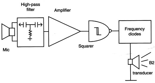
A small piezoelectric transducer is connected to this stage. Common tweeters are not ultrasonic transducers, but they can perform well with sounds up to 25 kHz, which is enough for our purposes. If the reader wants, he or she can look for piezoelectric ultrasonic transducers that provide higher frequencies.
The output of the filter is applied to the input of an audio amplifier. Again, the choice was the LM386, which can operate with signals as high as 300 kHz.
With a 10 µF capacitor in the feedback circuit, the gain will be 200 with frequencies of up to 30 kHz. The output of this amplifier is also an ultrasound signal, not heard by our ears.
The frequency conversion is made, passing the signal across a 4093 integrated circuit (IC) to convert it into square waves, and then a 4020 performs the division by 16.
Note: frequency division can also be performed by a microcontroller such as the Arduino. MSP430, PIC or other.
The result is shown in Figure 3, a square wave that has 1/16 of the original frequency picked up by the microphone.
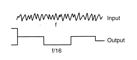
The output signal obtained in this stage is applied to & transducer for reproduction.
In the simplest way, the transducer is a high-impedance piezoelectric type, but the evil genius can add a transistor stage, such as the one shown in Figure 4, to drive a low-impedance earphone or a small loudspeaker. Also, the circuit is powered from AA cells.
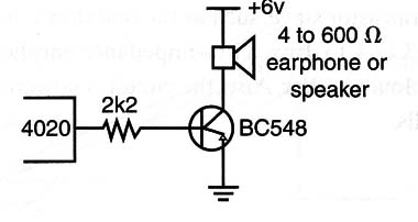
Figure 5 shows the schematic diagram of the bat ear.
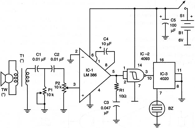
The circuit can be mounted on a printed circuit board (PCB), and the board suggested for this project is shown in Figure 6.
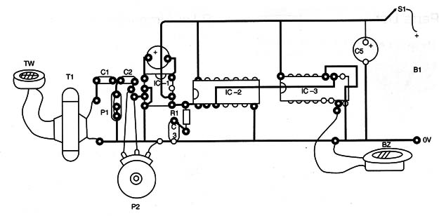
When mounting, the position of the polarized component must be observed. Any inversion of the ICs, the electrolytic capacitors, and the power supply can damage the components and prevent the circuit from operating.
For the transducer, any piezoelectric tweeter can be used. If a common low-impedance tweeter is used, a transformer is necessary (T1). Any output transformer found in an old-time transistor radio is suitable. The high-impedance coil is plugged into the circuit and the low-impedance coil to the tweeter.
Another solution is to take off the small transformer found inside the tweeter and plug the transducer directly into Cl and GND without the need of a transformer.
According to the characteristics of the transformer and the tweeter, the evil genius may have to make experiments with C1 and C2, altering the value and finding the best adjustment for P1.
Testing and Using
Place the cells in the cell holder and close S1. Put P1 in the position of maximum resistance and open the gain control (P2).
Beating on the tweeter with one’s fingers, the sound from BZ will be reproduced in the form of a lower-frequency signal. Sounds from one direction can be concentrated in the sensor (tweeter) using a parabolic reflector, as described in the bionic ear project in this site.
IC-1: LM386 integrated circuit audio amplifier
IC-2: 4093 CMOS integrated circuit
IC-3: 4020 CMOS integrated circuit
T1: Transformer (see text)
BZ: Piezoelectric transducer or earphone
TW: Tweeter (ultrasonic microphone; see text)
P1: 10 k ohm trimmer potentiometer
P2: 10 k ohm log potentiometer
R1: 10. ohm x 1/8 W resistor, brown, black, black
C1, C2: 0.01 µF ceramic or polyester capacitors
C3: 0.047 µF ceramic or polyester capacitor
C4: 10 µF x 12 V electrolytic capacitor
G5: 100 µF x 12 V electrolytic capacitor
S1: On/off switch
B1: A 6 V source or four AA cells
Other: PCB or solderless board, plastic box, knob for P2, wires, solder, etc.


