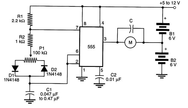
When the output of the 555 is at the high logic level, Bl supplies the current to the load. When the output is low, B2 supplies the current.
Notice that, when the duty cycle is 50% and the net power applied to the load is zero, both supplies (B1 and B2) are providing current, and the drained power is not zero. This fact should be considered when using this block.
This circuit can be adapted to work as a shield for microcontrollers receiving the control signal from an analog output of the controller.
Another point to be considered when using this circuit is that, when the applied power is zero (under the explained condition), the motor tends to vibrate at the oscillator frequency.
This can be avoided by using a capacitor wired in parallel with the motor or by choosing a convenient frequency for the oscillator. This means that, depending on the motor, experiments must be conducted to find the correct value of C1.


