

This article is part of my book Mechatronics Sourcebook in Portuguese now in a new version in English.
Relays are electromechanical switches. They are basically formed by a coil and one or more pair of contacts as shown by figure 1.
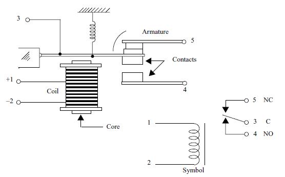
When a voltage is applied to the coil, the current flow creates a magnetic field that atracts the contacts closing them. If the current accross the coil is cut, the magnetic field disappears and the contacts open. An exernal circuit controlled by the contacts can be turned on and off by the current accross the coil.
Two important properties can be noted in this arranjement:
1. The controlled circuit is completelly isolated from the control circuit.
2. We can use low voltage and low current applied to the relay's coil to control high voltage and/or high current circuits.
The relays can be found in different sizes and electrical characteristics depending on their application.
The main characteristcs we must observe when using relays are:
a) The nominal voltage or coil voltage (Vcoil) - is the voltage that applied to the coil make the contacts close. In practice, the relay can close their contacts with voltages lower than the indicated and keep them closed even when the voltage falls bellow the nominal value presenting a characteristic of histeresis. Types with voltages between 3 and 48 V are common in robotics and mechatronics applications. Figure 2 shows this characteristic.
b) The coil current (Icoil) - is the current that flows accross the coil when the nominal voltage is applied. Currents between 20 and 100 mA are common in relays.
c) The coil resistance (Rcoil) - this resistance can easily be found dividing the nominal voltage by the coil current. Values between 50 Ω and 500 Ω are common.
d) Contact current (Icontact) - is the maximum current that can be controlled by a relay. Typical values are in the range from 1 to 10 amperes.
e) Type of Contacts - the relays are not simple switches controlled by currents. One coil can control one or more contacts in different configurations as shown by figure 3. This figure also shows the symbol and the aspect of common relays.
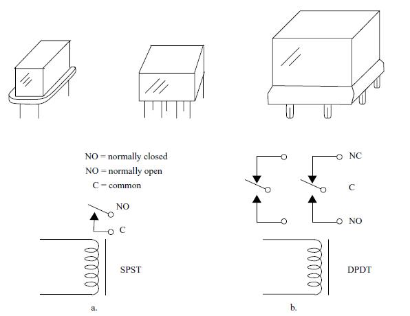
In (a) we have a SPST relay and in (b) a DPDT relay. Other types with multiples contacts can be found. So, the relays can act as SPST, DPDT or Multiple switches.
The next formulas are useful to know the third characteristic of a relay when two of them are giving:
Formulas:
a) Resistance of the coil when voltage and current are given
R = V/I
b) Current of the coil when the rssistance and voltage are given
I = V/R
c) Voltage of the coil when the current and the resistance are given
V = R x I
In some cases is important to know the power dissipated by a relay in an apllication. The next formulas can be used for this task:
Formula:
P = V x I = R x I2 = V2/R
Where:
P is the power dissipated by the coil of a relay (W)
V is the applied voltage (V)
I is the current through the coil (A)
R is the resistance of the coil (?)
5.1.1 - Special Types of Relays
a) Latch Relays - Latches or bistable relays are relays that turns on with a current flowing in a direction and keep this state even when the current is cut. To turn off the relay or to bring it back to the previous state is necessary to apply a new current in the coil but in the oposite direction. Some latch relays uses two coils, one to turn on and the other to turn off.
b) Solid state relays - these are special types where the contacts are replaced by some kind of solid state switch as a transistor, SCR, TRiac, etc. More information about these devices can be ound in other articles in this sites or books of the author.
c) Reed-relays - these are relays formed by a reed-switch and a coil in the disposition shown figure 4. The operation principle is the same of common relays: when a current flows through the coil the resulting magnetic field acts on the contacts of the reed switch closing them. Reed relays are small, very sensitive but can't handle large currents. Normally they are used to control currents up to some hundreds milliamperes.
5.2 - How Relays Are Used:
When using a relay we have to consider the device to be controlled (wired to the contacts) and dthe circuit that drives the relay.
The following itens consider the two parameters:
5.2.1 - Using the Contacts
Figure 5.5 shows how the contacts of the relays are used.
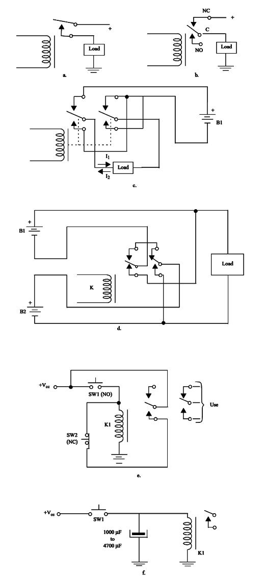
In this figure we have the next applications:
(a) Here we show the simplest application of the relay. It is used as a SPST switch controlling an external load. The load is on when a current flows accross the coil.
(b) Here we show how the NC (normally closed contacts) can be used to turn off a load when the relay is energized. This configuration is preferred when the time the load is on is larger than the time off.
(c) Here is shown how a DPDT relay can be used to control the direction of the current flowing accros a load. When the relay is off the direction of the current is I1. When the relay is on the direction is I2.
(d) In this application a relay is used to switch power supplies or loads, passing from series to parallel and vice-versa.
(e) Another interesting application is the one shown here. When SW1 is pressed one pair of contacts are used to latch the relay. To turn off the relay press by a moment SW2. See that SW1 is a momentarynormally open switch and SW2 is a momentary normally closed switch.
(f) Pressing by a moment SW1 the relay closes the contacts and remains in this state by a time interval determined by the value of the capacitor and the resistance of its coil. A sensor can be used as SW1.
5.2.2 - Drive Circuits using Sensors and Switches
Figure 6 shows many circuits that can be used to drive relays from low power on/off sensors or low power switches as reed-switches, mercury switches, blade sensors, pendulum sensors, and others. The current flowing through the sensor/switch is the current the coil need to close the relay's contacts.
An important application for this type of circuit is as a shield for microcontrollers. The current supplied by the outputs of a microcontroller is not always enough to trigger a relay directly or should we trigger many of them. This requires the use of special circuits shields as we give below.
Lets explain the operation and use of each configuration:
(a) This is the simplest configuration to turn on and off a relayn using a SPST switch or any other sensor. Se can be a momentary normally open (NO) or normally closed (NC) switch if this kind of action is needed in the application.
(b) Simple logic functions can be implmented using sensors or switches and a relay as shown in this cases. Here we have a 2-input AND gate using a relay. The relay will close the contacts only if the two switches (S1 and S2) are closed.
(c) A OR gate is implemented with a relay as shown here. The relay will close the contacts if S1 or S2 is closed.
(d) A two-way circuit can be implemented using SPDT switches or sensors as shown here. The relay is driven when S1 and S2 are both in A or both in B. In other conditions the relay is off.
(e) This circuit shows how a SPDT switch or sensor can be used to drive two relays.
(f) This configuration allows the control of two relays using two wires. When S1 is in A, D1 is forward biased and K1 closes the contacts. When S1 is in B, D2 is now forward biased and the relay K2 is enerized closing its contacts.
(g) Here we have a simple circuit to drive a DC relay from an AC souce. The
diode is a 1N4002 for voltages up to 50 V and currents up to 1 A. The
capacitor must be in the range between 1 µF and 100 µF.
h) This circuit is used to control two relays using a two wire line. Wen S1 is in (a) the AC voltage is applied to D1 and D2. D1 is forward biased with the positive half-cycles and D2 with the negative. The relays are ON. When K1 is in (b), D3 and D1 are forward biased with the positive half cycles and K1 closes the contacts. Passing now S1 to (c), D4 and D2 are forward biased in the negative half cycles of the AC voltage driving K2.


