
However, we have verified that it is possible to add control to this robot that walks without direction and this can result in an interesting project for teaching technology in middle school (STEM program).
Students can assemble the robot by learning the principle of circuit operation and then test their ability in a competition in which robots must cross a racetrack or even a track with obstacles, controlled by each competitor.
How to assemble the brush robot with a remote control trough flashlight is what we will see in this article.
The version we present uses a flashlight to control the direction of movements of the robot.
With this the robot can be directed by the students and a competition involving obstacles or skills can be programmed.
The circuit is more complex than the original version with only one motor, being assembled by high school students who must weld the components on a printed circuit board, or in a simpler configuration, on a terminal bridge.

How it works
The idea of making a walking brush is simple.
We incline the plastic bristles of the brush, which is done by the same process described in the previous design, using hot air for this purpose.
This hot air can be obtained from a hairdryer, for example, as shown in Figure 1.

By placing a small electric motor on the brush and on its axis a weight so that it becomes unbalanced, and when it rotates it also vibrates, this vibration is transferred to the bristles, as shown in Figure 2.

As a result, the vibrations cause the bristles to move so as to provide the driving force of the motor.
The brush then walks in the direction determined by the orientation of the bristles.
In the original version of the Brush Robot, described in a another article, there was no control at all.
The robot simply walked, hitting obstacles and changing direction in a totally erratic way.
The idea of having control over the robot came from the Combat Robot, which is another project that we described in an article and used with our students.
If we have two propulsion motors, shifted in a way which the force tends to move the robot in one direction and the force of the other in the opposite direction, controlling the motors, we can direct the small Brush Robot, as shown in Figure 3.

So, if the two engines are driven at the same time, the robot will go straight forth.
Turning the right side motor (B) the motor will move to the left side and the left side motor (A) it will drive the motor to the right side, as shown in Figure 4.
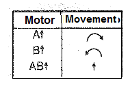
Obviously, unlike the combat robot, we do not have the reverse movement, because even with the inversion of the motors, the robot continues to move in the direction determined by the bristles of the brush.
The drive mode of the engines we chose comes from another project of ours: the mechatronic vehicle VM-1 which evolved to the versions VM-2 and VM-3.
We then initially used two driven circuits, one for each motor, having two LDR sensors.
Thus, when we focus a flashlight to one of the LDRs the corresponding motor is triggered and the robot goes in the direction of command.
Likewise, when the other LDR is illuminated, the corresponding motor is triggered and the robot changes direction.
In Figure 5 we show how to use a motor control circuit with LDR.

In Figure 6 we have the circuit used to control a motor, using a power Darlington transistor.

These transistors have a very large gain, being able to receive the signal of the LDR, even in very weak light, and still drive the engine at full power.
In the tests we did with our first prototype, we found that the robot responds to commands very quickly, which makes it harder for controller using a flashlight.
The robot then turns quickly from one side to the other and focusing the flashlight to the corresponding LDR is not very easy, not even for students used to the fast operations of video games.
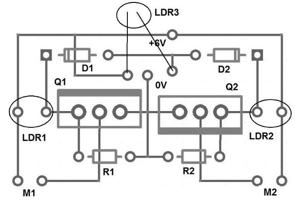
To facilitate control, we have decided to add a third LDR to the circuit so that when it is illuminated, it triggers both motors at the same time.
With that, to make the robot advance in a straight line, we no longer need to quickly focus the light between the two side LDRs, which is not very easy.
Just illuminate this third centralized LDR, as shown in Figure 7.

This LDR is connected to the two control circuits through diodes, which prevent the interaction between the circuits.
This way, our robot can be controlled in a simpler way:
a) Illuminating the LDR 1 the robot turns left
b) Illuminating the LDR 2 the robot turns right
c) Illuminating the LDR 3 the robot advances straight
Assembly
Electronic Part
The complete circuit of the Brush Robot 2 directed by the focus of a common flashlight is shown in Figure 8.

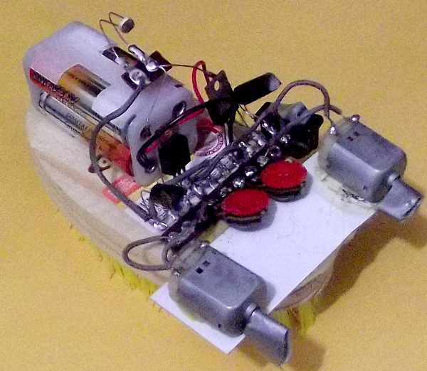
In the initial experimental version we assembled we used two small terminal bridges as a chassis for the components, as shown in Figure 9.

In this assembly, we use fixed resistors (R1 and R2 of 10k) instead of the trimpots indicated in the diagram as P1 and P2, but this is optional.
The circuit may also be built on a printed circuit board as the drawing shown in Figure 10.
Mechanical Assembly - Step by Step
a) Prepare the brush by bending the bristles in one direction so that it can walk in a straight line. Use a hot air dryer for this purpose.
b) After the brush has been prepared, cut a piece of plastic (it can be an ordinary ruler) with a length of 8 to 10 cm, and width of 3 to 4 cm as shown in Figure 11.

Glue this piece of plastic to the brush at the position shown in the figure.
c) Then, disconnect the motors temporarily from the board or bridge and glue them to the “ruler” with the axes facing back in relation to the motor movement. Figure 12 shows how to do this.

Subsequently, when the board or bridge is attached, the motors will be reconnected. For gluing use strong glue as the vibration of the engine will tend to release it, if the glue is not good.
d) Then, prepare two counterweights with a nut or washer, attaching it to the motor shaft as in the previous design, and as shown in Figure 13.

It will be important to run tests for the best washer or nut size be used considering the robot performance. A very small washer or nut will cause the robot to vibrate without leaving its place.
e) The next step is to attach the battery holder to the brush.
Electronic Assembly – Footsteps
1. Cut 6 pieces of thin flexible wire approximately 12 cm each and weld them in positions corresponding to M1, M2, 0 V and +6 V, as shown in Figure 14.

2. Fit and weld the transistors, observing the position of the fins. Weld the terminals under the board and cut the excesses.

3. Weld the resistors R1 and R2 in the indicated positions. Bend their terminals so they are upright. There is no polarity for these components.

4. Weld the diodes (D1 and D2) by observing their position. Note that the stripe indicating the diode cathode should be according to the position of the stripe marked on the board for each of them.

5. Weld the LDRs. See that they are high on the board, that is, with long terminals, to facilitate their positioning in the control.

6. Make the interconnections according to the diagram.

Inter connections:
a) M1 and M2 wires connected to the motors (any polarity)
b) +6 V wire to one of the switch poles
c) 0 V wire mended to the black wire (negative) of the battery holder
d) Weld the red wire from the battery holder to the other pole of the switch
7. Protecting LDRs - Because the circuit is very sensitive, LDRs must be provided with small shields which we build by wrapping a small piece of insulation tape in each one, as shown in Figure below.

This feature prevents ambient light from interfering with the control, which will mainly occur if its movement occurs in a very bright place.
The power comes from four small batteries, which provide enough power for a good movement of the robot.
The polarity of the battery holder must be observed, because if there is a reversal, the circuit will not work.
Electronic Part Test
After completing the assembly, check the connections of all the components and turn on the power after placing the batteries in the holder.
If the transistors and batteries become hot, turn the circuit off immediately (acting on the switch) and check if the diodes are in the correct positions. They may be inverted.
Separately, illuminate the LDRs to verify if the motors respond to commands.
If, when lighting the LDR 3 only one motor runs or no motor runs, check if one of the diodes, or both diodes, is inverted.
With the electronics working, we can pass to the mechanical part.
Note: in this project, the direction of the motor rotation is not important.
Completing the Assembly
If its version is the bridge one, attach the bridge to the position shown in Figure below. See also the photo of our prototype.

If the version is built on the printed circuit board, usually with the motors glued, it stays in the operating position if rigid wires are used.
Weld the engines again.
Position the LDRs so that they receive light from the flashlight in the position indicated in the figures.
Check the assembly, and if everything is in order, move on to the next item.
Test and Use
Place the batteries in the holder, and take the robot to a place that is not very bright. Turn on the key, which powers the circuit.
First, hold the robot in your hand without placing it on the ground.
Then, illuminating the LDRs with the flashlight, check if the motors are working as indicated.
Lighting up the LDR1 engine 1 works, illuminating LDR2 the engine 2 works and illuminating the LDR3 the two engines work.
If, when illuminating the LDR3 only one motor works, one of the diodes may be inverted and if the two do not work, the two diodes may be inverted.
Put the robot on the ground and try to control it with the flashlight.
If the robot tends to deflect a direction when LDR3 is illuminated, the bristles may be crooked.
Another possibility for difficult control is the position of the battery holder and the center of gravity of the design. You can try displace the battery holder by changing its position.
Another possibility is to place counterweights, for example, lead fishing weights on one side to correct the tendency of it to turn to only one direction.
If the movement is too slow, the bristles may require a larger position change or heavier counterweights must be used on the motor shafts.
With good training you will be able to drive your robot with a flashlight.
Competition
Several types of competitions can be programmed with the brush robot.
The first consists of a race with obstacles in which the robots must travel a certain distance facing obstacles which can be pins with different colors.
The colors of the pins will determine the points lost on the course.
In case of a tie in points lost, it is worth the time of arrival.
The second possibility is for each competitor to travel a certain distance on an obstacle course, counting the obstacles, which were knocked down.
Improvements to the original design can be made with the implementation of wireless remote controls, Wi-Fi using a tablet or smartphone.
a) Electronics Part
Q1, Q2 - TIP120 - Power Darlington NPN Transistor
LDR1, LDR2, LDR3 - Small Round LDRs
P1, P2 - 10k trimpots or fixed resistors of 1k to 10k
D1, D2 - 1N4148 - general purpose diodes
M1, M2 - 6 V direct current motors
S1 - Single switch
B1- 6 V - 4 small alkaline batteries
Miscellaneous:
Terminal bridge or printed circuit board, wires, 4 small battery holder, welding, etc.
b) Mechanical part
13 cm brush, plastic ruler, glue, washer or nut, insulation tape, etc.


