

There are two basic gear arrangements of gears shown by figure 1.
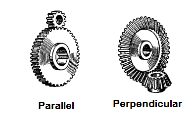
Obs: when two gears of unequal size are combined the smaller is usually called a pinion.
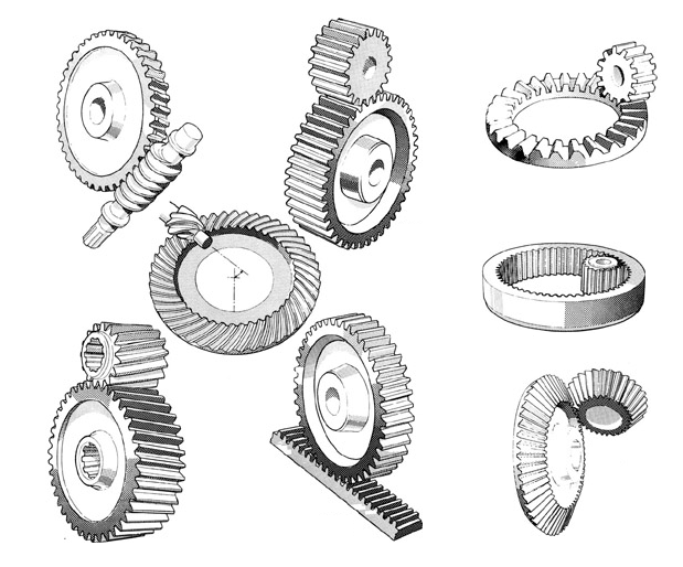
Figure 2 shows other types of gears.
Formulas
a) Speed change
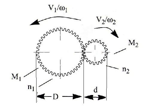
v1/v2 = n1/n2 (linear) (1)
ω2 / ω1 = n2/n1 (angular)
Where:
V1 and V2 are the tangential speed of the gears
n1 and n2 are the number of teeths
ω1, ω2 are the tangential speed in rad/sec
b) Mechanical Advantage:
TMA = V2/V1 (2)
TMA = n2/n1 (3)
or
TMA = ω2 / ω1 (4)
Where
TMA is the theoretical mechanical advantage:
V1 and V2 are the tangential speed of the gears
n1 and n2 are the number of teeths
ω1, ω2 are the tangential speed in rad/sec
c) Torque Change
TMA = n1/n2 (5)
Where: n1 is the number of teeth on the driven gear
n2 is the number of teeth on the driven gear
M2/M1 = n2/n1 (6)
M2/M1 = V1/V2 (7)
M2/M1 = ω1 / ω2 (8)
Where:
M1 and M2 are the turning moment
V1 and V2 are the tangential speed of the gears
n1 and n2 are the number of teeths
ω1, ω2 are the tangential speed
Obs: friction is disconsidered
d) Teeths versus diameter
n1/n2 = d/D (9)
Where:
n1 and n2 are the number of teeths
d and D are the diameter of the gears
Figure 3 shows all the situations involved in the previous formulas.
Gear Boxes
Gear boxes are used to change speed or torque in mechatronic projects. The number, the size and and the number of teeths determine the TMA of a gearbox or the number of times the torque or the speed is multiplied.
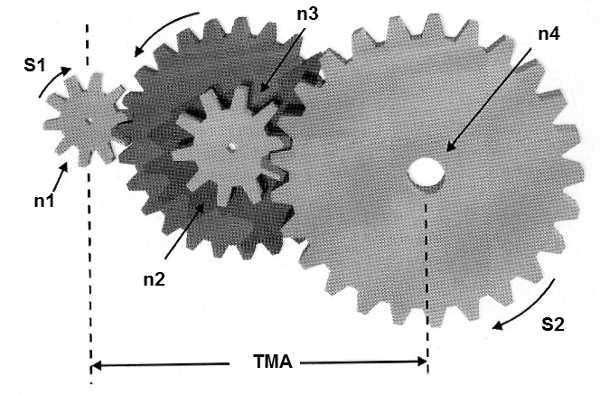
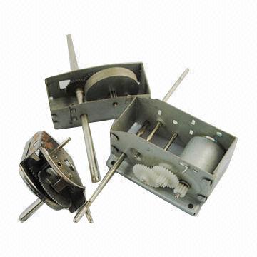
Figure 4 shows some gearboxes used to change the speed and increase the mechanical advantage.
Commercial types of reduction boxes are found with the most diverse relations of gears and TMA. When choosing a reduction box for your project make sure it supports the mechanical effort that must be subjected to your project.
Formulas
a) Changing the speed: (refer to figure 4)
S2 = S1 x T1/T2 (10)
Where:
S1 is the speed of the first shaft in train
S2 is the speed of the last shaft in train
T1 is the product of the teeth on all drivers
T2 is the product of teeth oin all driven gears
Speed can be calculated in revolution per second, cm/s (tangential) or degrees per second (angular)
b) Changing the Torque: (refer to figure 4)
TMA = T1 / T2 (11)
Where:
T1 is the product of the teeth on all drivers
T2 is the product of teeth on all driven gears
TMA is the theoretical mechanical advantage
Obs: friction is disconsidered
The Bevel Gear
Bevel gears are used if the shafts are not parallel as shown by figure 5. They are used to change the direction of a motion.
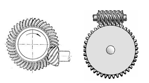
Figure 6 shows two main types of bevel gears: the mitter gear and the spiral gear.
For the mitter gear the formulas given in item 2.6 are valid.
For the spiral bevel gear the next formula is valid:
Formula
v = n1 x 2 x π x R (12)
Where:
V is the tangential speed of the circular gear
n1 is the number of steps advanced by the worm in one turn or revolution
π is the constant 3,14
R is the radius of the circular gear (diameter/2)
Note: this article is part of our book “Handbook of Mechatronics”.


