The idea of designing a single control module with relays that can operate in the two basic types of configurations (monostable and bistable) comes from the constant need that designers of automatisms, robots, mechatronics and control devices must repeatedly use these settings.
With a single module, easy to assemble and change the programming of the operating mode, already containing trigger circuits, we need few external interface elements to implement a project.
With this, the reader who likes to create new projects, who wants to experiment and develop or even teaches, can have a very useful resource for his/her work, which is a module with ready-made functions.
The module we describe has the following characteristics:
It has programmable timing control in two ranges for monostable configuration. It is possible to generate trigger time intervals of up to 30 minutes.
Possibility of using the two relays in independent configurations: monostable and bistable. The two circuits have separate triggering elements.
6 or 12 V supply depending on the relay used. If relay support is used, simply change the relay to use the module with a different power supply.
Consumption in the very low rest condition, which allows its use in applications fed by alkaline or other batteries.
Optional monitoring for operation.
Inputs and outputs connected by single terminals, making it easy to use in development, didactic or experimental assemblies.
Among the projects in which we can use the module we highlight the following:
Robots
Mechatronics arms
Automation of conveyor belts or assembly lines
Object count
Experimental Elevators
Opening and closing doors
Intelligent alarm systems
Home automation
Let us analyze its principle of operation, because understanding it will make it easier for the reader to develop his own projects.
HOW IT WORKS
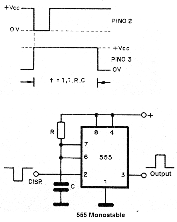
The input circuit, where the control signals are applied, has two accesses, one for each integrated circuit 555. These inputs are connected directly to the trigger pin (2) of the integrated circuit 555.
The triggering is done by a negative transition of the voltage applied to these pins.
When the voltage at any of these inputs drops to a value below 1/3 of the supply voltage (Vcc) the output of the integrated circuit (pin 3) that was at 0 V goes to the high level, near Vcc.
The time that the output remains on, that is, with an available positive voltage depends on the time constant RC given by the resistor and capacitor connected together to the pins 6 and 7 of the integrated circuit 555.
This time is approximately given by:
Since R is a trimpot in series with a resistor, we can adjust the time in a wide range of values.
Going further, two capacitors built on the board allow us to select the range of performance periods by a switch or a jumper, depending only on which component the reader wants to use.
For a simple conformation of the output pulse (anti-peaking circuit), we choose shorter periods (capacitor of lower value) when we have a short rectangular pulse at the output.
For a long-time output, we choose the highest value capacitor.
The limit values for R and C in this circuit are R = 2 200 ohms and C = 1 000 uF when we get timings that exceed half an hour.
In Figure 1 we have the waveforms in this circuit.
An interesting option for the project is to use the CMOS equivalent of the bipolar 555. The TL7555 supports higher values of capacitors (which must be very low leak types), exceeding 1 hour.
A second programming system, which can be made by keys or jumpers, is connected to pins 3 of each IC. With it we can directly trigger the transistor drivers of the relays in monostable mode in one of the positions.
At the other programming position, we have the application of the rectangular output pulse of 555 at the flip-flop input of type D, constants of integrated circuit 4013, which forms the next block.
With this feature we have a bistable operation.
The 4013 is a double flip-flop type D, capable of directly driving the transistor drivers of the relays.
For each pulse obtained at the output of 555 we have a change of state of the flip-flop output, as shown in Figure 2.
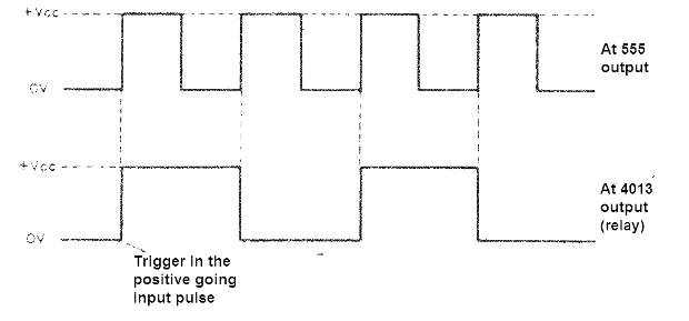
See, then, that for every two output pulses of the 555 we have a pulse at the base of the transistor, which means that in a first command order the relay docks, and in a second order it pushes off. The control cycle can be repeated indefinitely.
The 555 used with a short output time serves as an efficient anti-knock circuit, ie, capable of avoiding the production of two or more input commands in a single drive, what would happen if we connected directly to the input of the 4013 sensors equipped with mechanic contacts.
Each relay has two contacts that operate in both the NO (normally open) and NC (normally closed) configuration. We only connect one of the contacts of each relay to the output, leaving the other as an option for activating an indicator LED or a parallel load.
Note that in the NO configuration the relay docking energizes the load, while in the NC configuration, the relay docking de-energizes (turns off) the load.
The power supply is not included in the project because it depends on the application.
For 6 V or 12 V relays, the components are the same. In Figure 3 we give a suggestion of 6 V power supply that can power a module and also some other loads as small motors.
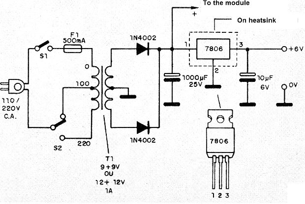
The integrated circuit of the voltage regulator of the source should be provided with a heat radiator.
ASSEMBLY
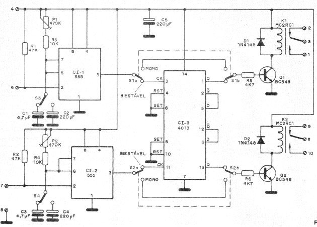
The complete diagram of the Control Module is given in Figure 4.
The printed circuit board is given in Figure 5.
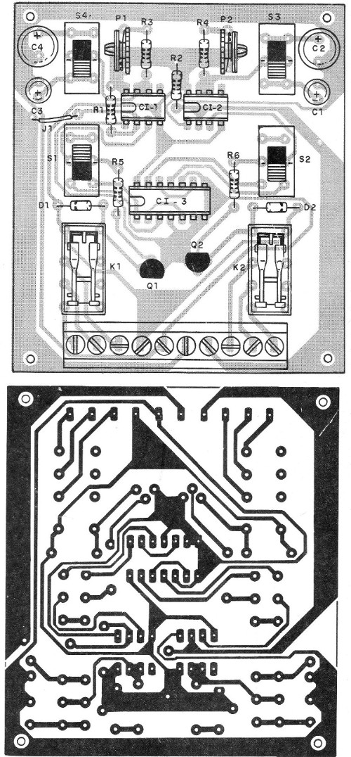
There are several options for the control output. A screw bar can be used for an experimental version which facilitates the connection of the external and trigger devices.
However, for a definite or economical assembly, the wire connections can be direct.
For functions we also have two possibilities. We can use keys of 2 poles x 2 positions, as in the prototype of the photo, as we can use jumpers that will be placed in the functions that we want.
The recommended relays are those of general use, with coil current of max. 100 mA for 6 V and 50 mA for 12 V, with contact currents of 1 A or more.
These relays have a base that fits into 14-pin DIL sockets for integrated circuits. The use of the socket facilitates the replacement of the relays according to the supply voltage.
We use only one of the relay contacts from the relay on the board, possibly the other one being used in another function in which case the wires must be welded under the board.
TEST AND USE
Initially, check the entire assembly by attaching the integrated circuits and relays to the sockets if using them. Watch their positions well, as a reversal can burn them.
If you use the S3 and S4 monostable switches, set them for shorter periods. If your assembly is switchless, weld the jumpers for this purpose by placing the 4.7 uF capacitors in the circuit.
The trimpots should be in their positions of least resistance. The switches S1 and S2, if used, must be in the mono position. If not used, place jumpers in the corresponding position.
Only then we can connect the power supply. The positive pole of the source goes to pin 4 of the board and the negative to pin 5.
Now using a piece of ordinary wire, ground for a moment the entrance of each monostable. To do this, just put together the wire tips and the terminals 5 and 6 at the same time to trigger CI-1 by activating K1 and between 5 and 7 to trigger CI-2 and activate K2.
The trigger of the relay can be noticed by the click of its contacts at that moment. However, the reader can connect an external load for this purpose. Figure 6 shows how to connect a LED to monitor the drive during the operation check.
Once the test is done in the monostable operation, we can start the bistable test. For this we change the positions of the keys S1 and S2 or the programming by jumper of those places of the board.
The trimpots should be placed in the positions of least resistance with the smaller capacitors in the circuit.
As in the previous test, we re-energize inputs 5, 6 and 7 of the module. In this case, however, the relay should pop when activated, but should not shut down.
To disconnect we must touch the input terminals again.
To use the module, remember that:
K1 is driven by the signal applications at input 6 and P1 controls the periods of the mono version. S3 is in charge of selecting the periods and S1 the mode (monostable, bistable). The control outputs of this sector are terminals 1 (NO) and 2 (NC). Pin 3 is the common terminal.
K2 is driven by the application of signals on pin 7. P2 controls the monostable periods selected by S4. S2 determines the mode of the operation (monostable or bistable). The outputs are pins 8 (common), 9 (NC) and 10 (NO).
The settings are all independent for the two sectors.
For very short drive intervals, in more critical applications it is recommended to reduce C1 and C3 to 100 nF (ceramic or polyester).
Semiconductors:
CI-1, CI-2 - 555 - integrated circuits, timers
CI-3 - 4013 - CMOS integrated circuit, type D flip-flop
Q1, Q2 - BC548 or equivalent - general purpose NPN transistors
D1, D2-1N4148 or equivalent - silicon diodes
Resistors: (1/8 W, 5%)
R1, R2 - 47 k ohms - yellow, violet, orange
R3, R4 - 10 k ohms - brown, black, orange
R5, R6 - 4.7 k ohms - yellow, violet, red
P1, P2 - 220 k ohms or 470 k ohms - trimpots
Capacitors:
C1, C3 - 4.7 uF x 12 V - electrolytic
C2, C4, C5 - 220 uF x 12 V - electrolytic
Miscellaneous:
S1, S2, S3, S4 - 2-poles x 2 positions switches - optional - see text
K1, K2 - 6 or 12 V relays - depending on the power suply - see text
A printed circuit board, 10-bolt bridge (optional), DIL sockets for ICs and relays (optional), wires, welder, etc.


