There are also sensors that include digital processing circuits and therefore can only be used with microcontrollers. The signals generated by the circuits embedded in these sensors are sent through parallel or serial communication through interfaces such as I2C.
To work with these sensors, the reader must know the type of signal produced, consulting the manufacturer's datasheets and knowing how to program the microcontroller to interpret and use these signals.
The main types of sensors in this category are:
Pressure sensors (barometric)
These sensors have small openings with access to a diaphragm. This way, the external air pressure on the diaphragm can be measured by a chip placed just below it.
The diaphragm makes contact with the chip so that the pressure on it changes its electrical characteristics.
Usually these circuits operate with a bridge circuit as shown in the figure.
Inertial sensors
These sensors measure variations of the figure that acts on a sensitive element which may be a small mass or a vibrating blade.
In one case, the sensor detects the force acting on the mass when it is on acceleration or even when a force acts directly on the sensitive element.
This type of sensor can be used to sense sudden changes in the position of an object or even in balance.
The type of vibrating blade is also called a gyroscope serving to detect variations in speed and direction of movement of a moving object in which it is installed.
In the most common applications, these sensors are provided in development boards that allow their direct connection to a microcontroller.
Nuclear radiation sensor
The most common type of sensor is the Geiger-Müller valve.
Geiger-Muller valves are sensor valves which detect ionizing radiation (atomic radiation).
This device is based precisely on the fact that if a high energy particle crosses a rarefied gas it causes its ionization and thus makes it momentarily conductive in its trajectory.
Thus, this valve is constituted by a metal tube with an opening which is a mica window, as shown in Figure 1.
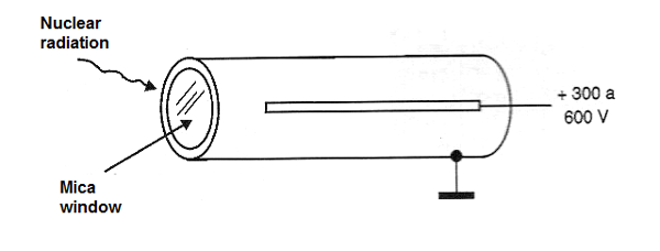
Mica is used because it is more transparent to lower penetration radiations such as alpha and beta particles, which does not occur with glass and other materials.
A second electrode is placed in the middle of the tube and between them a very high potential difference is established, usually between 300 and 800 V.
The tube contains an inert gas under low pressure in a way that under normal conditions it is insulating.
However, when an ionizing particle enters the tube, the gas in its path becomes conductive and with this it is possible to circulate a current pulse between the electrodes, as shown in Figure 2.
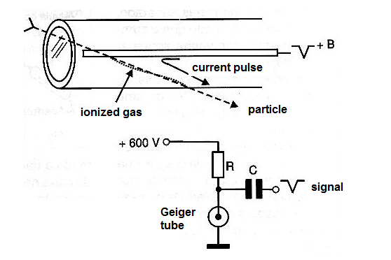
In a circuit as shown in Figure 2, the pulse appears on the load resistor R and is transferred via C to an amplifier and then to a headset.
The passage result of the ionizing particle by the gas produces of an audible "click" on the handset.
The amount of clicks then indicates the amount of particles that are penetrating the tube and causing the ionization.
This means that when we approach a Geiger detector from a radioactive material, as shown in Figure 3, the frequency of the clicks will increase.
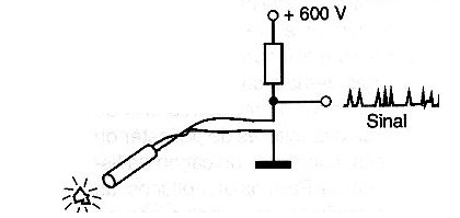
Of course, instead of the headset we can have other ways of indicating the level of radiation.
One is the use of a small speaker.
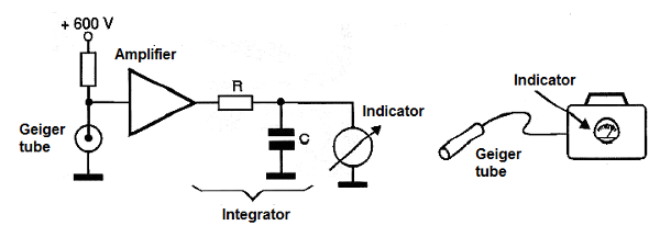
Another is to add an integrator circuit that "sums" the pulses and triggers a pointer indicator, as shown in Figure 4.
Radiation can also be detected using a semiconductor sensor consisting of a large surface diode.
We can also use an ion chamber as the radiation sensor. In it the passage of an ionizing particle causes ionization of the air around it, making it conductive and thus enabling the circulation of a current.
How to use resistive sensor
When using resistive sensor the designer must keep in mind some important questions.
How much the resistance changes in the desired operation conditions?
The range of resistance of a sensor is important to design or choose the circuit. If a sensor changes only few ohms its resistance when excited the circuit must have special characteristics to see this small change.
LDRs changes the resistance in a large range of value, so they are easy to use. NTCs, depending on the type also have a large range of resistance, but others as pressure sensors not.
Is the current sourced by the sensor enough to drive a circuit?
If the sensor have a large reistance drop when excitated the current can be enough to drive any circuit. In general, to drive a block with a bipolar transistor the resistance in the low value condition must be bellow 50,000 ohms., If Darlington transistor, CMOS ICs or Two Stages circuits are used, this resistance can be higher, in the range of 200,000 to 1,000 000 ohms. As a general rule, if your sensor doesn't trigger the circuit, try another block with more sensivity.