In a robot or radio-controlled vehicle, this device is used to measure the acceleration or braking intensity or, in a curve, the force that appears as a result and which may eventually alert the danger of a tipping.
Another possible application for the apparatus is in physics experiments, where we can measure the degree of acceleration or braking of moving objects or still due to the action of springs and other mechanisms.
The device can also be used in the car to give indications of "uprooting" or even braking.
The system used in the device is very simple: a weight which moves with the acceleration, leaving the normal balance position triggers a potentiometer, which is the transducer.
The current consumption of this circuit is extremely low and it can easily be installed in a small plastic box.
For the car, the indicating instrument can be fixed to the panel.
HOW IT WORKS
The force acting on a body withdrawing it from a vertical resting position depends on the acceleration to which it is subjected, as shown in Figure 1.
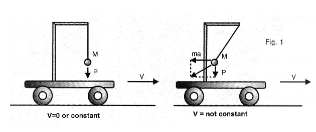
Thus, by attaching a certain mass to the axis of a common potentiometer of the rotary type, it tends to be in a position of equilibrium when at constant or stationary speed.
However, for any acceleration (positive or negative) it tends to move out of balance and trigger the axis of the potentiometer in proportion to the existing acceleration.
Now that the potentiometer is coupled to an indicating circuit, this circuit will be responsible for showing the value of this acceleration in an instrument, quite accurately if properly calibrated.
In our case, the indicator circuit is a Wheatstone bridge in which one of the arms is just the sensor potentiometer used and the indicator is a common microammeter.
Thus, by zeroing the instrument, with the bridge in equilibrium in the absence of acceleration (acceleration = 0), we set the instrument in conditions to measure accelerations.
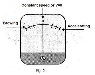
The instrument used in our case is a microammeter with zero at the center of the scale, but even other types can be used as long as we take care that in the position of the balance the pointer is in the center of the scale, as shown in Figure 2.
In the final version, we use a 7806 voltage regulator to reduce the 12 V or more of a car battery to 6 V stabilized circuit power.
However, for battery power only remove this voltage regulator from the circuit.
ASSEMBLY
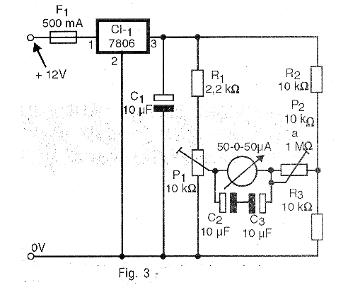
In Figure 3 we have the complete diagram of the accelerometer.
The arrangement of the components on a terminal strip, which is the simplest form of assembly, is shown in Figure 4.
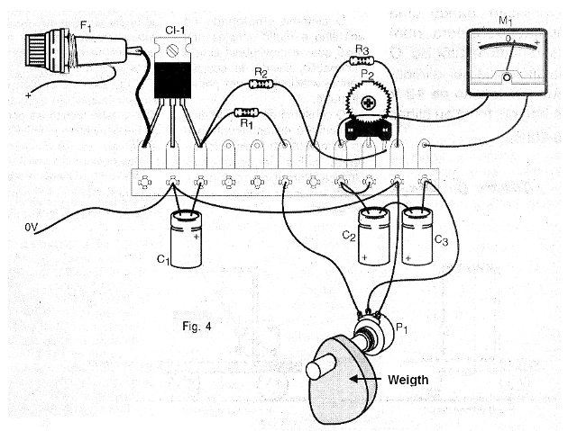
We opted for the use of a terminal bridge given the simplicity of the circuit, but nothing prevents more skilled readers from using a printed circuit board.
The voltage stabilizer 7806 does not need a heat radiator and the potentiometer P1 must be linear.
This potentiometer must have adapted the drive mechanism to the weight.
The drive system is shown in Figure 5.
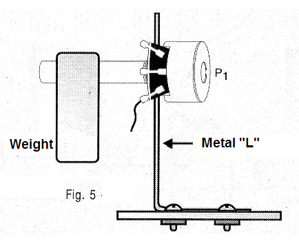
The weight should be high enough to be able to move the potentiometer shaft easily.
If possible, the skilled reader can open the potentiometer and decrease the force that the pressor spring makes on the resistive element so that it becomes softer and thus is more easily driven by weight.
The resistors are 1/8 W and the capacitors C2 and C3 are not critical in order to avoid very sudden movements of the indicator needle.
The indicator instrument is a 50 uA microammeter with zero in the center, but microammeters up to 500 uA can be used.
P2 is a common trimpot.
ADJUSTMENT AND USE
To adjust, switch on the unit and place the P1 axis so that the weight in the rest position brings the instrument to half scale.
Then lightly adjust the weight P2 so that the needle movements are not too abrupt.
If necessary, increase the value of P2 to 1 M ohms in order to obtain the best performance range of the instrument depending on the characteristics of the instrument used.
Depending on the full scale and the resistance, it may be necessary to change the values of some components for a smooth and precise drive.
Once you have checked the operation and made the adjustment, it is only to make your final installation where you want to monitor the acceleration.
The weight must be oriented in such a way as to move with the force acting on it due to the acceleration to be measured.
The input positive is connected to any positive point of the wiring of the car, if this is its use, and the zero point volt to any point of the chassis or the negative of the source.
For use in robots and other mechanisms the power can be removed from the circuit.
An independent power supply can be made using 4 standard batteries.
In this case, the voltage regulator (7806) can be removed from the circuit.
Semiconductors:
CI-1 - 7806 - integrated circuit voltage regulator
Resistors: (1/8 W, 5%)
R1 - 2.2 k ohm - red, red, red
R2, R3 - 10 k ohm - brown, black, orange
P1 - 10 k ohm - linear potentiometer
P2 – 10 k ohm at 1M ohms - trimpot
Capacitors:
C1, C2, C3-10 uF / 6V - electrolytic
Miscellaneous:
F1 - 500 mA - fuse
M1 - 50-0-50 uA - microammeter with zero in the center of the scale
Terminal strip, weight and mechanical sensor system, mounting box, wires, welding, etc.