
The speed of a small DC motor depends on the mechanical load attached to it. This speed can be controlled by changing the voltage applied to the motor and thus the current through its coils.
In short, we can control the speed of a small motor with the use of a rheostat connected in series with its power, as shown in Figure 1.
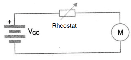
What we have then is a linear speed control which acts directly on the power of the motor which depends on the mechanical load.
This type of control has several disadvantages. One of them, and the main one, is that the constant speed can not be maintained at low rotations, because the variation of the load reflects in the circuit with losses of power and even oscillations.
Another rather unpleasant problem in this circuit is that it cannot provide a smooth starting for the motor that tends to "jump" when the minimum voltage pulls it from the rest is reached.
This erratic behavior of linear controls can however be eliminated by using a PWM or Pulse Width Modulation control.
What is a PWM?
If we take into account that the power and therefore the speed of a small DC motor depends on the applied voltage we can use an interesting device to vary this power without, however, modifying the voltage applied to the motor.
The idea is to work with time as a second variable in the control circuit.
If we apply to the motor rectangular pulses that have the nominal motor voltage but which last 50% of the time, ie, an active cycle of 50%, as shown in Figure 2, we can say that the average power of the motor will be 50% of the Maximum.
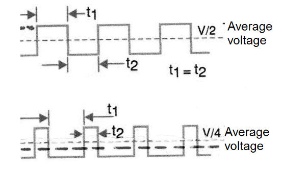
However, as each pulse has the maximum rated voltage, the motor does not feel with the inertia that occurs when we apply low voltages while maintaining its torque.
To increase the applied power, obtaining a higher speed simply increase the width of the pulse, and to decrease the speed or power applied, simply decrease the speed of the pulse.
In short, we can control the velocity but keep the torque in a range closer to the maximum, modulating the applied impulses in its width, hence the name of this technique widely used in mechatronics applications at all levels.
See then that an engine that has this type of control can rotate without almost losing the torque from zero, achieving very low revolutions, impossible to obtain with a linear control.
The PWM Control
A typical PWM control is then formed by a rectangular oscillator which has the active cycle set through a potentiometer.
The signal from that oscillator is then applied to a power device which can be either a power field effect transistor (power MOSFET) or a power Darlington.
The typical frequency of such a circuit will be between 50 and 2,000 Hz depending on the motor used.
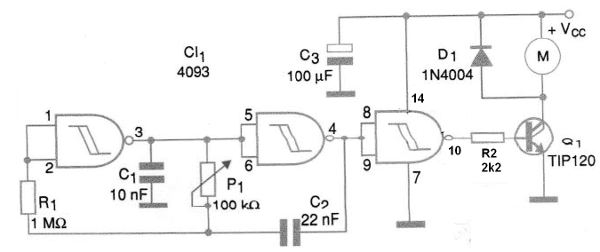
In our circuit, we use a circuit 4093 to form the oscillator having the active cycle and hence the modulation controlled by P1. Other rectangular oscillators that may have the changed active cycle will also work in similar configurations.
The same oscillator circuit can also be made with NAND or NOR ports such as 4001 or 4011, however, given the non-triggering characteristics of these Cis, the circuit may generate a bit more interference or oscillations.
Assembly
In Figure 3 we have the complete PWM control circuit for motors between 3 and 12 V. The maximum current will depend on the transistor used.
We suggest experimenting with an array of contacts and then transferring it to a universal board with the same pattern.
The components are not critical but the transistor must be fitted with a heat radiator if the current required by the motor is greater than 200 mA.
The same arrangement applies to the Darlington TIP120, TIP130 and other transistors of the same series as well as to the MOSFET power transistors of the IRF series.
The power supply may be either batteries or external power supply which provides the current required by the motor.
The capacitor C2 should eventually have its value altered to avoid the "small punches" that can occur at low speeds with certain types of motors. The capacitor C3 may also be changed in order to obtain the best power with the motor used.
For R3 the value depends on the transistor used. It can be 1 k ohms for power MOSFETs and 4.7 k ohms for power Darlingtons.
The diode D1 has the purpose of preventing the high voltage generated in the motor by switching to go back to the transistor and then cause it burning.
Test and Use
Just plug the circuit into the power supply and a DC motor into its output. Acting on P1, a change of its speed must be observed, without appreciable loss of power.
If the engine tends to swing or lock at certain rotations, change C2 and C3.
The same circuit can also be used as dimmer or digital power control for the brightness of incandescent lamps, strength for solenoids and also temperature for small heating elements based on nichrome resistors.
CI-1 - 4093 - CMOS integrated circuit
Q1 - TIP120 or IRF630 (Power Darlington or MOSFET - see text)
D1 - 1N4004 - silicon diode
R1 - 1 M ohm x 1/8 W - resistor - brown, black, green
R2 - 2k2 x 1/8 W - resistor - red, red, red
R2 - 1k to 4k7 - resistor - brown, black, red or yellow, violet, red - see text
C1 - 10 nF - ceramic or polyester capacitor
C2 - 22 nF - ceramic or polyester capacitor
C3 - 100 uF x 16 V - electrolytic capacitor
M1 - 3 to 12 V direct current motor - see text
P1 - 100 k ohm - linear potentiometer
Miscellaneous:
Protoboard or universal circuit board, batteries or power supply, wires, potentiometer button, welding, etc.


