Double Solenoid Actuators
A simple arrangement of two solenoids is used in many direction controls and actuators as shown in Figure 1. When solenoid X1 is on, the robot turns to the left, and when the solenoid X2 is on, the robot turns to the right.
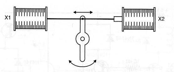
Other applications include mechatronic actuators, such as the one shown in Figure 2, that can be used to move an object.

As the reader can see, in this application, only one solenoid can be on at a time.
The following blocks are circuits to drive two solenoids in this type of application.
Intelligent Control for Two Solenoids
The circuit shown in Figure 3 avoids the forbidden condition in which the two solenoids are activated at the same time.
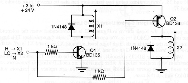
When the input is at the high logic level or receives a signal of up to 1 V, solenoid X1 is on and X2 is off. When the input is set to the low logic level or to the ground, solenoid X1 is off and X2 on.
The transistors are chosen according to the current required by the solenoids.
In the site you can find information about meny power transistor that can be used in this circuit. The base resistor can also be altered in the range between 1 to 10 k according to the gain of the transistors installed and the current required by the solenoids.
Intelligent Solenoid Control Using Darlington Transistors
The same conúguration described in the previous block, but using NPN and PNP Darlington transistors, is shown in Figure 4. This configuration needs less current to be driven. Only a few milliamperes are need to drive solenoids with currents up to severa] amperes, depending on the transisto.
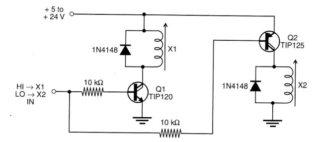
In particular, we recommend this configuration to drive high-current solenoids from Microcntrollers, TTL or CMOS outputs.
Note: Equivalent configurations using a PNP bipolar transistor and a PNP Dar-
lington transistor can be easily implemented, based on the circuits shown in this site. . Configurations using two transistors can also be derived from other circuits.
Intelligent Control Using CMOS Logic
In particular, the block shown in Figure 5 is recommended when the solenoids are controlled by CMOS logic. You can replace the IC with the equivalent TTL function. When the input is at the high logic level, solenoid X2 is on and X1 is off. At the low logic level, solenoid X2 is off and X1 is on.
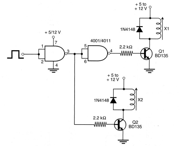
When using as shield you only have to power the CMOS with 5 V. The transistor stages can be powered from 5 to 12 sources, according the solenoid.
When using the BD135 solenoids, up to 1 A can be driven. The reader must experiment with resistor values if other transistors are used. Darlington transistors can be used if high-power solenoids are installed. You can replace the resistors with 10 k units in this case.
Intelligent Circuit Using CMOS IC and Power CMOS
The circuit shown in Figure 6 is ideally suited to be driven from CMOS logic and microcontrollers.
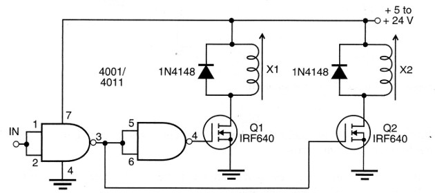
Any CMOS function that can be used to invert the logic is suitable for this application. The power MOSFETs are chosen according to the current requirements of the solenoids.


