How do small DC motors work, such as those found in battery toys? How can I change the direction of rotation? If the reader is curious about the radio control or just picked up some toy from a relative child to repair, certainly have thought about these issues and become really curious about having the right answers.
In fact, these small engines, because of their small size and efficiency, catch the attention of the hobbyist, even more if we consider the enormous range of sizes and types in which they exist.
Small DC motors, as the name suggests, are designed to work with batteries, with voltages in the range of 1.5 to 12 V and with tiny powers, which are usually in the range of a thousandth horsepower.
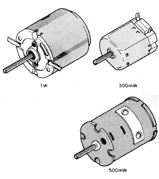
But even a thousandth of a horse, when conveniently used, can perfectly carry a toy cart or a snack bar to a considerable speed. (Figure 1)
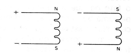
As the readers who accompany us know, a coil formed by many turns of an enamelled wire, when traversed by an electric current, creates a magnetic field in the same way as a magnet whose polarity depends on the direction of the current.
We can reverse the polarity of the magnetic field simply by reversing the direction of current flow. (Figure 2)
Operation
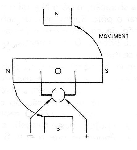
Well, in the structure indicated in Figure 3, starting from the initial situation in which the coil is aligned with the magnet, we circulate a current in a certain direction.
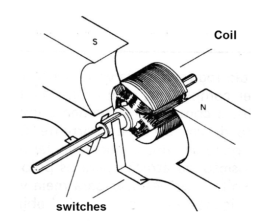
This direction is such that the magnetic field of the magnet interacts with the field of the coil itself, causing it to move, the poles of the coil are attracted by the opposing poles of the magnet and repelled by the poles of the same name.
North attracts south, but north repels north and south repels south.
The result is the movement of the coil in the direction that the poles of different names approach.
But, the coil is built in such a way that two switches are in action. (Figure 4)

The function of this switch is to invert the direction of the current flow in every half turn of the coil. But, why?
To facilitate the analysis of its action, and the complete operation of the motor, let's call N and S the permanent magnet poles, and A and B the coil poles.
We then start from the initial situation, shown in (1) in Figure 5.
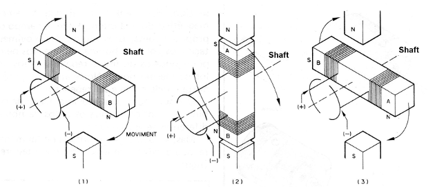
In this situation, the N pole attracts the A pole and the S attracts the B pole, viewing the direction of the current circulation which is forced to circulate through the coil. The clockwise movement starts.
Soon, the poles A and B of the coil which moves are approaching the poles of the magnet that attracts them, the reversal of the direction of the current occurs by the action of the switch, shown in (2).
The result is that now, pole N will repel pole A and attract B, while pole S will attract A and repel B.
With the beginning of the movement, the inertia acquired by the coil causes it to continue its movement now towards the new position determined by the attraction of the magnet, that is, half a lap beyond.
But as soon as this half-turn is over, as shown in Figure 3, the switch again reverses the direction of current flow.
The result can be imagined by the reader, is that the pulling position for the coil poles returns to move half a turn further, thus forcing the coil rotor to continue moving.
As much as the coil rotates in the direction of finding its position of balance, this will never be reached, because always when this instant is to arrive, the polarity is inverted by the commutator and the movement continues.
As long as there is current circulating through the coil and therefore the supply of electrical energy to the motor, it rotates and with that we can achieve mechanical strength.
The reader should have realized that if in the initial situation the polarity is reversed in the power supply, the pole that will attract the coil at its end A will no longer be the N, but the S and the movement will start in the opposite direction. (Figure 6)
The speed of rotation of these small motors depends on several factors, such as their own mechanical constitution and also the supply voltage, without mentioning the load, that is, the force that must be done.
One way of controlling the speed of such an engine is through the applied voltage, and for this there are several possibilities.
SPEED CONTROL
The simplest control we can have for a small motor is a wire potentiometer, or rheostat, which is connected in series, as shown in Figure 7.
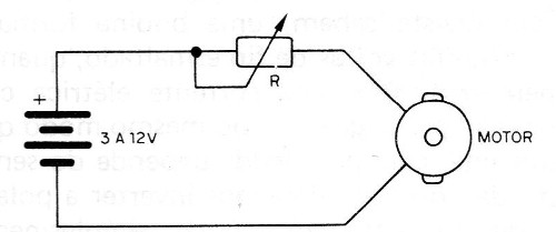
However, this process has several drawbacks, such as the fact that the potentiometer must dissipate a good power, tending to heat up.
Not enough, this control does not maintain the torque of the motor, that is, its force, at low rotations.
With a control of this type, the motor does not accelerate linearly, but it gives a "jump" and leaves already with certain speed when we open a little the power.
The electronic controls, in addition to being more efficient in harnessing the power supplied by the source, which does not dissipate, like the potentiometer alone, also allow to maintain the torque and the linearity in the acceleration.
In Figure 8 we show a simple electronic rheostat control, in which the potentiometer is replaced by a transistor, which, however, acts in almost the same way.
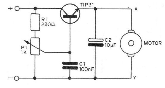
The advantage in this case is only in the power dissipation or loss in the form of heat which is much smaller, allowing the use of a common potentiometer of low dissipation.
The control shown is suitable for motors from 3 to 12 V with currents up to 500 mA.
The assembly on a small terminal bridge is shown in Figure 9, noting that the transistor must be provided with a heat radiator, especially if the motor under control requires, under maximum conditions, a current of more than 100 mA.
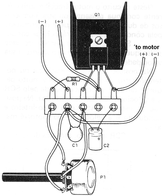
For greater currents, the transistor can be the 2N3055 with a good heat radiator.
At the potentiometer connection, it is very important to correctly choose the order of the terminals so that the acceleration occurs when we rotate its axis to the right and not the other way around.
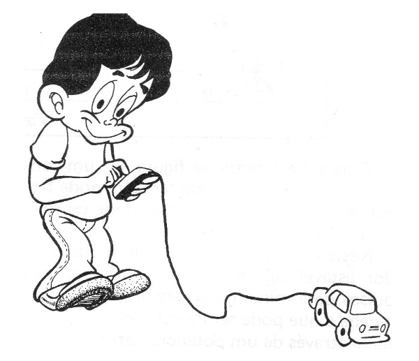
In Figure 10 we suggest the application of a control of this type in a control "with a wire" of a toy car.
If the motor can be powered by the local network, through a transformer, as with an autorama, or with an electric train, it is possible to perform the pulsating speed control with SCR, as shown in the circuit of Figure 11.
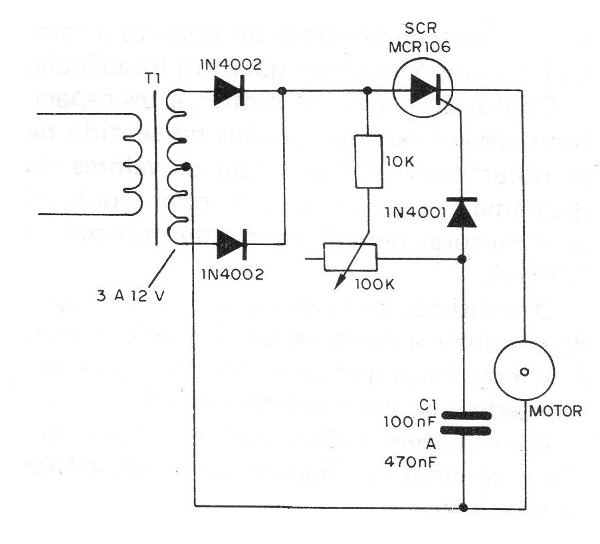
In this circuit the motor works with pulsing continuous current, that is, with pulses of variable duration, which is determined by the conduction of the SCR. The conduction angle of the SCR determines the portion of each pulse that reaches the motor and, therefore, its speed.
In the highest resistance position of the potentiometer only a very small portion of each pulse is driven by the SCR and the motor speed is minimal. In the lowest resistance position the entire pulse is driven and the motor speed is at maximum.
With the indicated SCR, motors of currents up to 1 A or more can be controlled with supply voltages between 3 and 12 V.
It should be noted that there is a small voltage drop in the SCR, of the order of 2 V, which must be foreseen, and also that, for currents above 200 mA, it must be built on a good heat radiator.
The transformer must have the same supply voltage of the motor, since after the rectification occurs a rise of peak value, which in turn is compensated in the fall in the SCR.
The current of the transformer must be the maximum current demanded by the motor.
Finally we have in Figure 12, a pulse control, but it can also work with pure direct current, i.e., from batteries.
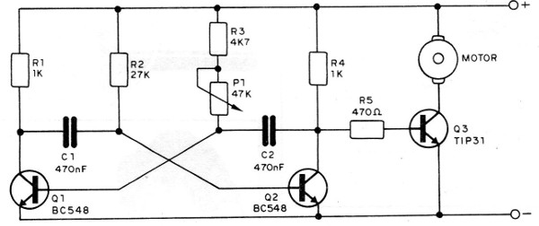
In this case, what we have is an astable multivibrator whose frequency and symmetry of the pulses determine the power that the motor receives and that can be modified in a good range through a potentiometer.
It is the capacitors C1 and C2 which determine the control range of the circuit and also the behavior regarding the frequency.
Depending on the type of motor, these capacitors must be modified in order to achieve higher torque. For the values ??of the diagram, a good control is obtained with motors of 6 V and maximum current of 500 mA.
The output transistor (03) must be capable of conducting the current required by the motor, and if it exceeds 100 mA, it must be built on a good heat radiator.
Assembly can be done on a printed circuit board or terminal strip.
In Figure 13 we give our suggestion of building.
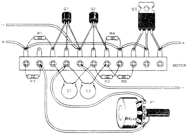
The transistors Q1 and Q2 can be of any NPN type of general use and the resistors all of 1/8 W. The capacitors are ceramic or of polyester, with values ??between 100 nF and 470 nF.
The better value will depend on the type of motor the reader wants to control.
Likewise, small changes in the values ??of the resistor R2 and potentiometer may be necessary to cover the full range of the motor and to obtain greater power.
PROBLEMS
There are several types of problems that small DC motors can have.
The main one is the formation of an oxide layer on the copper foils which, in most types, acts as a contact for the switches. Under these conditions the engine may refuse to start or even fail.
The solution, in this case, consists of cleaning with sandpaper to remove the oxide layer.
Another problem is the deterioration, which ultimately impairs the contact of the blades. In this case, the solution consists of forcing the rotor blades closer so as to re-contact and if possible, until they can be changed.
In certain types of engines some "carbon brushes" can be found on the commutator which, over time, eventually wear out. The solution in this case consists of their replacement.


