Relays are electromechanical switches. They are basically formed by a coil and one or more pair of contacts as shown by Figure .1. When a voltage is applied to the coil, the current flow creates a magnetic field that attracts the contacts and closes them. If the current across the coil is cut, the magnetic field disappears, and the contacts open. An external circuit controlled by these contacts can be turned on and off by the current across the coil.
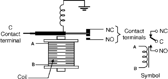
Two important properties can be noted in this arrangement:
1. The controlled circuit is completely isolated from the control circuit.
2. We can apply low voltage and low current to the relay’s coil to control high voltage and/or high-current circuits.
Relays can be obtained in different sizes and with different electrical characteristics as appropriate for a given application.
When using relays in these projects, we must observe the following characteristics:
The nominal or coil voltage. This is the voltage that, when applied to the coil, makes the contacts close. In practice, a relay can close its contacts with voltage lower than indicated, and keep them closed even when the voltage falls below the nominal value, demonstrating the characteristic of hysteresis. Relays with nominal voltages between 3 and 48 V are common in robotics and mechatronics applications.
The coil current. This is the current that flows across the coil when the nominal voltage is applied. Currents between 20 and 100 mA are common in relays.
The coil resistance. This resistance can be found easily by dividing the nominal voltage by the coil current. Values between 50 and 500? are common.
Contact current. This is the maximum current that can be controlled by a relay. Typical values are in the range of 1 to 10 A.
How Relays Are Used.
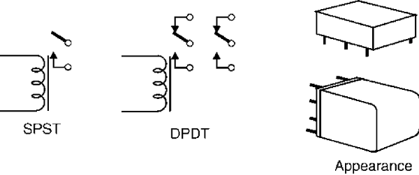
Figure 2 shows the symbol and the appearance of common relays. A relay can be considered as a switch that is operated by an electric signal. Figure .2a shows an SPST relay, and in 3.2b a DPDT relay. Other types, with multiple contacts, can be obtained.
Basic circuits Using Relays
The following are blocks that use relays and some passive components such as diodes, resistors, and capacitors. More complex applications, including other elements coupled to the relays, will discussed in later parts of this book.
Turning a Load On or Off
An important detail to observe in these relays is that they can have contacts that are normally open (NO) or normally closed (NC) as shown in the symbols. The simplest way to control a load from a relay is to use one of these contacts and the common (C) as shown in Figure 3.
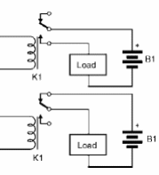
If the NO and C contacts are used, the load is powered on when the relay closes the contacts (when its coil is energized). If the NC and C contacts are used, the load is turned off when the relay is energized. This means that you can use the relay to turn loads on or off. Remember that the contacts are closed only while current is flowing through the coil.
Current Reversion
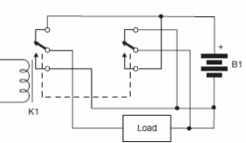
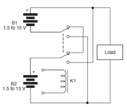
Another use for a relay is to reverse current, as described when using the DPDT switch. The relay is used as shown by Figure 4.
Series–Parallel Switching (II)
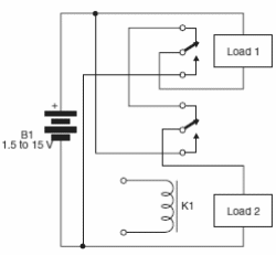
The circuit shown by Figure 5 switches two loads, connecting them in series or parallel to a power supply. When the relay is on, the loads are connected to the voltage source in series. When the relay is off, the loads are connected in parallel. The circuit can be used to boost dc motors in robotics and mechatronics devices. The same circuit can be used in an inverse mode, switching the loads in parallel when the relay is on.
Locked Relay
When S1 is momentarily pressed, the relay closes its contacts and remains in this state until the supply voltage is cut off. S1 can be any sensor, microswitch, or other momentary contact switch as suitable for the application. If a DPDT relay is installed, the second pair of contacts can be used to control any external circuit, as suggested in Figure 7.
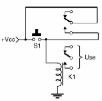
To turn off the circuit, you can simply cut off the power supply voltage, but there are other possible approaches. One of them is to create a momentary short using a switch in parallel with the coil. Another solution is given in the next block.


